Radial line slot antenna having a conductive layer

a conductive layer and antenna technology, applied in the direction of basic electric elements, electrical equipment, electric discharge tubes, etc., can solve the problems of several deficiencies in the practical implementation of swp sources, and achieve the effect of enhancing the robustness of a surface wave plasma (swp) sour

Inactive Publication Date: 2008-03-13
TOKYO ELECTRON LTD
View PDF10 Cites 6 Cited by
  • Summary
  • Abstract
  • Description
  • Claims
  • Application Information

AI Technical Summary

Benefits of technology

[0009]According to one embodiment, a system for enhancing the

Problems solved by technology

However, the practical implementation of SWP s

Method used


Image

  • Radial line slot antenna having a conductive layer
  • Radial line slot antenna having a conductive layer
  • Radial line slot antenna having a conductive layer

Examples


Embodiment Construction

[0032]In the following description, to facilitate a thorough understanding of the invention and for purposes of explanation and not limitation, specific details are set forth, such as a particular geometry of the plasma processing system and various descriptions of the system components. However, it should be understood that the invention may be practiced with other embodiments that depart from these specific details.

[0033]Nonetheless, it should be appreciated that, contained within the description are features which, notwithstanding the inventive nature of the general concepts being explained, are also of an inventive nature.

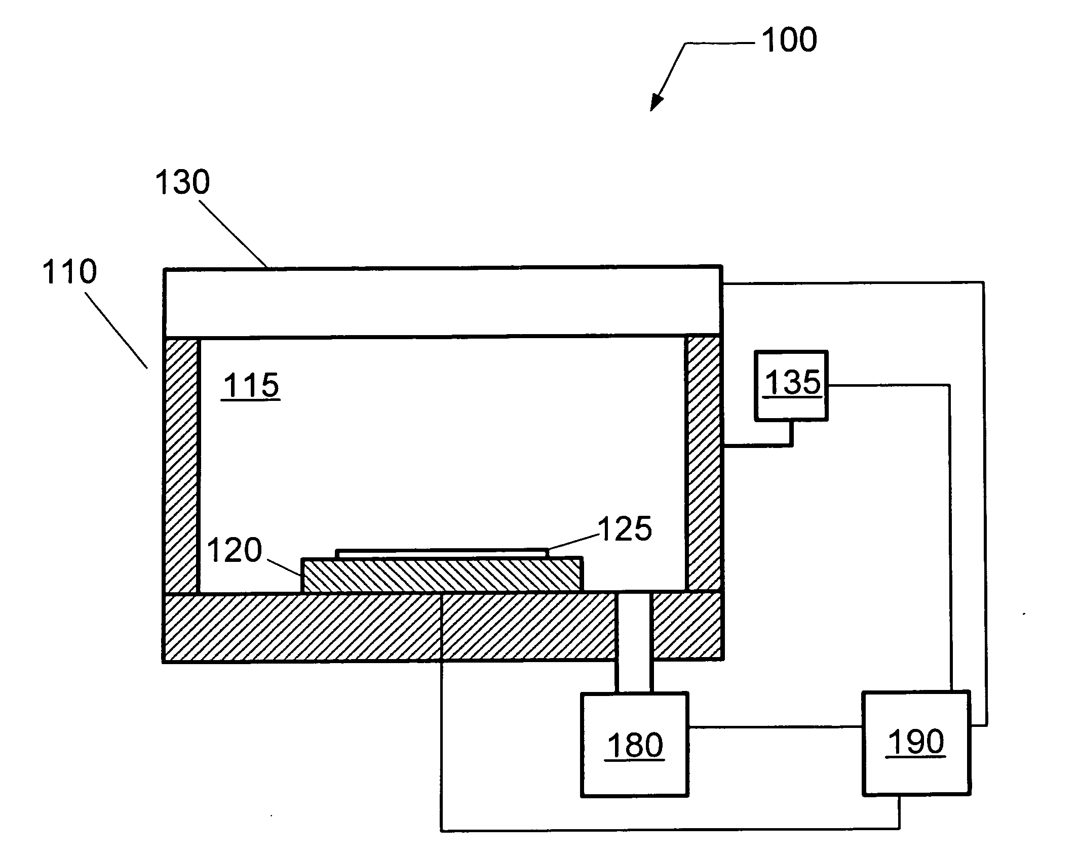
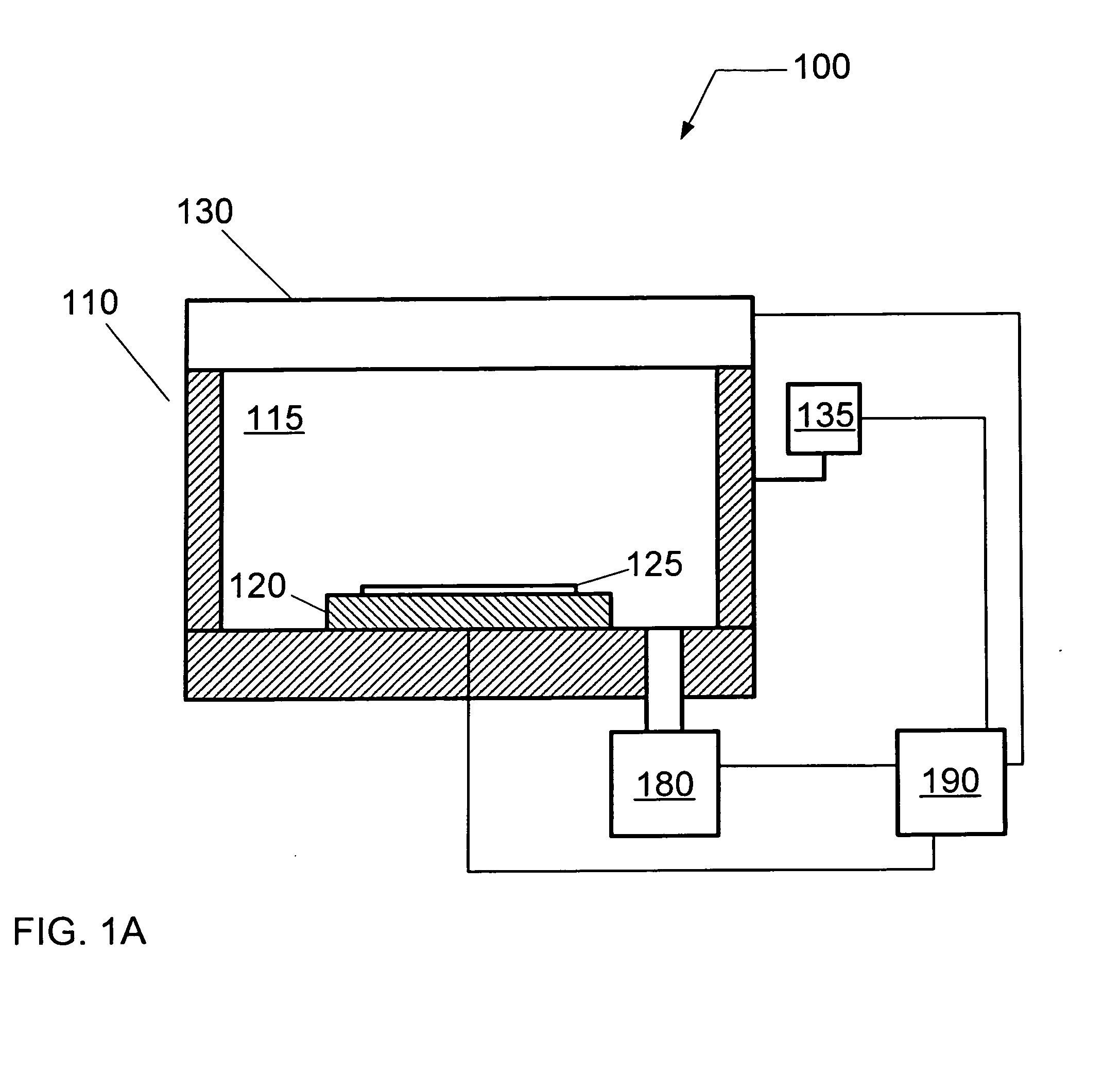
[0034]Referring now to the drawings, wherein like reference numerals designate identical or corresponding parts throughout the several views, FIG. 1A illustrates a plasma processing system 100 according to an embodiment. The plasma processing system 100 may comprise a dry plasma etching system or a plasma enhanced deposition system.

[0035]The plasma processing s...


PUM

PropertyMeasurementUnit
Thicknessaaaaaaaaaa
Electric potential / voltageaaaaaaaaaa

Abstract

A radial line slot antenna (RLSA) is described for generating plasma during semiconductor device fabrication. The antenna comprises a resonator plate having a partially open, electrically conductive layer coupled to a surface of the resonator plate. For example, the electrically conductive layer is formed at an interface between the resonator plate and the plasma.

Description

CROSS-REFERENCE TO RELATED APPLICATIONS[0001]This application is related to pending U.S. patent application Ser. No. 10 / 953,802, entitled “Surface wave plasma processing system and method of using”, Attorney docket no. 258536US, filed on Sep. 30, 2004; pending U.S. patent application Ser. No. 10 / 954,086, entitled “Method for treating a substrate”, Attorney docket no. 258538US, filed on Sep. 30, 2004; pending U.S. patent application Ser. No. 10 / 953,801, entitled “Plasma processing system for treating a substrate”, Attorney docket no. 258470US, filed on Sep. 30, 2004; pending U.S. patent application Ser. No. 10 / 953,791, entitled “Method and system for improving coupling between a surface wave plasma source and a plasma space”, Attorney docket no. 258537US, filed on Sep. 30, 2004; and co-pending U.S. patent application Ser. No. 11 / ______, entitled “Electron beam enhanced surface wave plasma source”, Attorney docket no. 291410USUS, filed on even date herewith. The entire contents of all...

Claims


Application Information

Patent Timeline
IPC IPC(8): C23F1/00
CPCH01J37/32192H01J37/32247H01J37/3222
Inventor CHEN, LEEMOROZ, PAUL
Owner TOKYO ELECTRON LTD
Why Eureka
Try Eureka