Brake disc structure with composite materials

a technology of composite materials and brake discs, applied in the direction of brake discs, braking elements, actuators, etc., can solve the problems of high manufacturing cost, increased cost, and high material cost, and achieve the effect of low manufacturing cos

Inactive Publication Date: 2008-03-13
METAL INDS RES & DEV CENT
View PDF8 Cites 36 Cited by
  • Summary
  • Abstract
  • Description
  • Claims
  • Application Information

AI Technical Summary

Benefits of technology

[0009]In view of the above problems in the conventional art, the present invention provides a brake disc structure with composite materials, which is used to meet the requirement of having abrasion resistance, light weight, and low manufacturing cost for a brake disc at the same time.

Problems solved by technology

However, these materials are usually very expensive, which may increase the cost and make the production insufficient.
Hence, for a long time, the graphite composite materials or ceramic composite materials cannot be used to produce brake discs.
In spite of the advantages such as a preferred heat dissipation capability as well as light weight, the aluminum alloy still cannot pass the rigid test on the abrasion resistance of a disc, which has a significant impact on the safety of the brake.
However, current tests in the field show that these surface modification techniques still cannot solve the problem of the low abrasion resistance.
Thus, it is obvious that a technical bottleneck still exists in the application of light materials such as aluminum alloy in the fabrication of a brake disc.
However, the manufacturing cost of this kind of material is relatively high.
Although the brake disc is claimed to have a high heat dissipation capability and a high abrasion resistance, the safety of brake is still not stable due to the unsatisfactory mechanical properties and insufficient abrasion resistance under a high temperature of the material.
Accordingly, the application of either graphite or ceramic composite materials may cause an increase in the overall cost.
Besides, no matter the aluminum alloy using an atomization forming technology and even applying a surface modification technology, or adding ceramic particles to fabricate a brake disc, the disadvantage of a low abrasion resistance of the above-mentioned conventional brake discs still exists.

Method used


Image

  • Brake disc structure with composite materials
  • Brake disc structure with composite materials
  • Brake disc structure with composite materials

Examples


Embodiment Construction

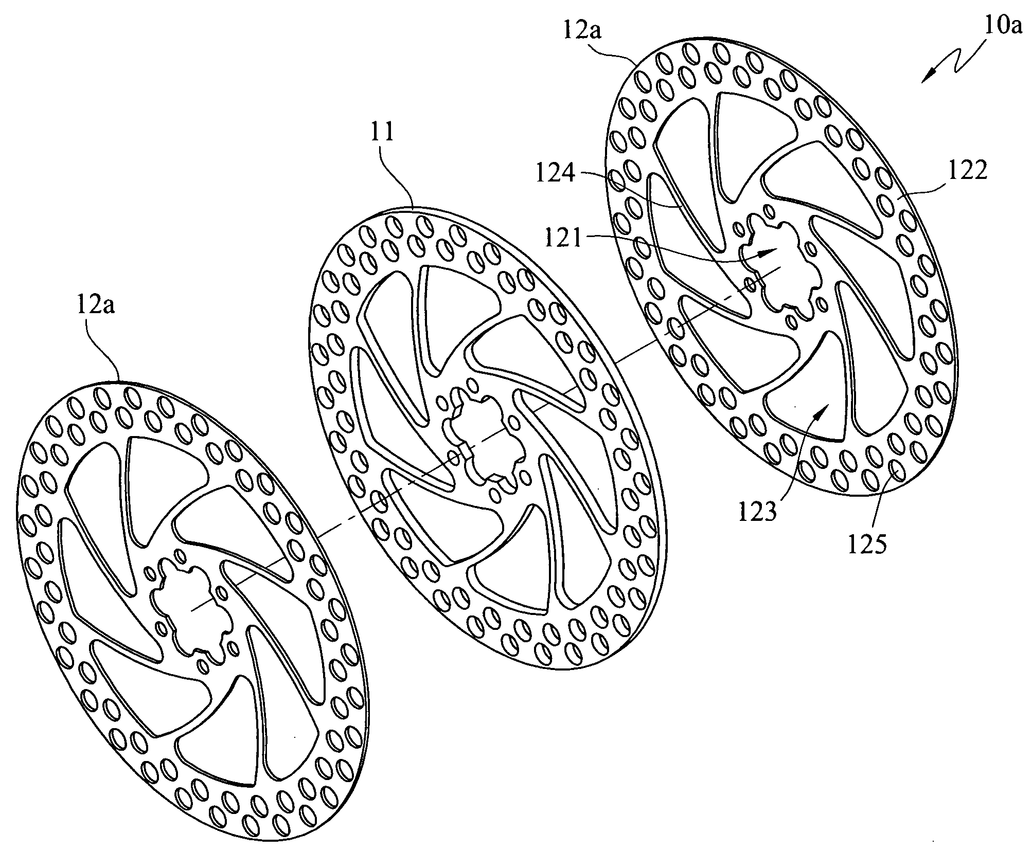
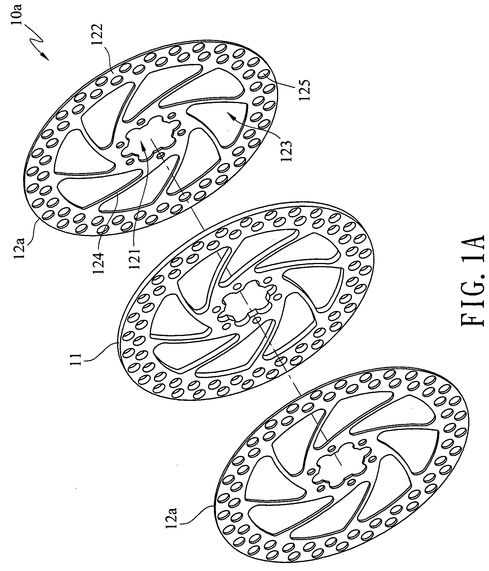
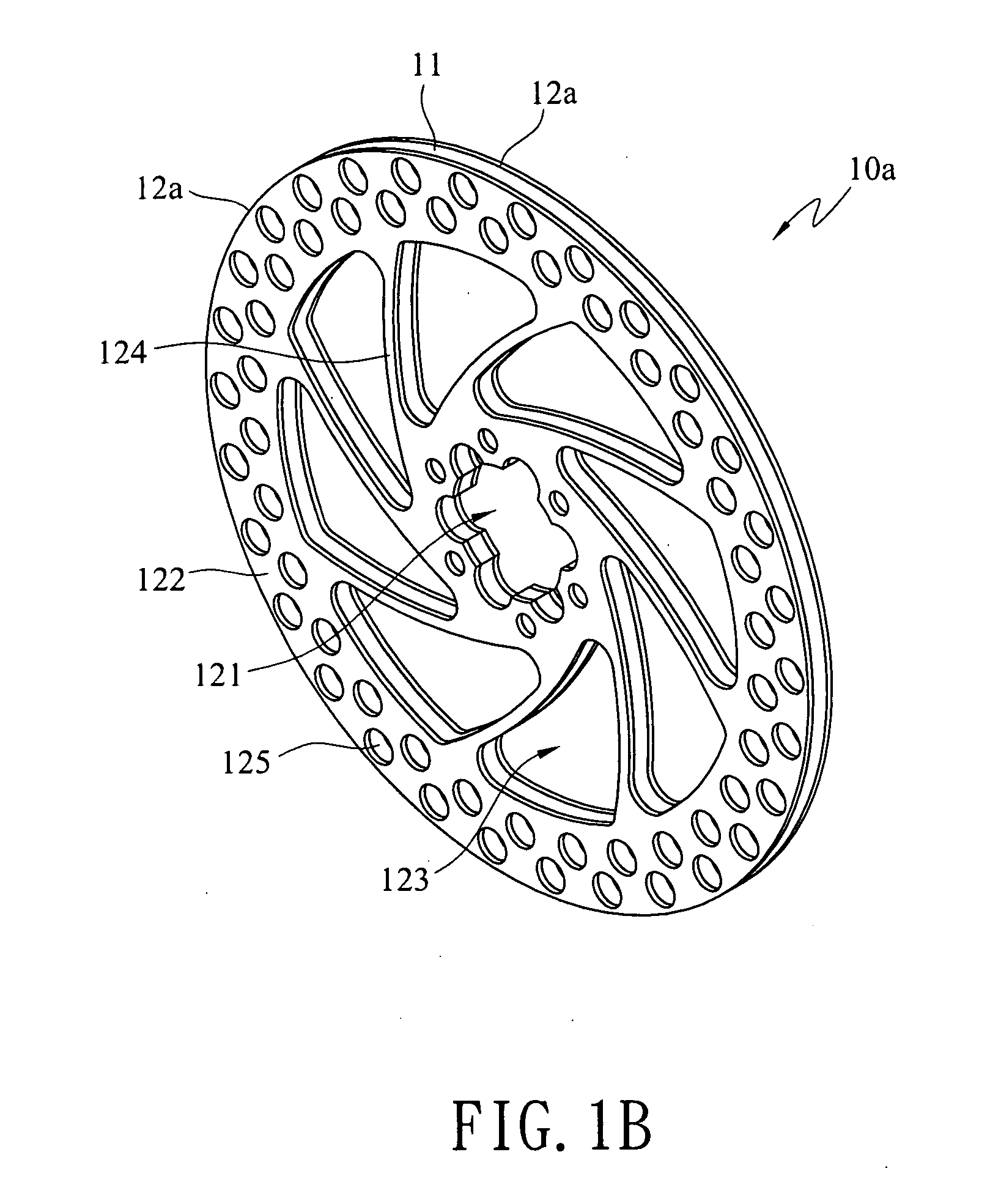
[0023]FIGS. 1A and 1B show a first preferred embodiment of a brake disc structure with composite materials according to the present invention. The brake disc structure with composite materials 10a includes an inner disk 11 and at least two outer disks 12a. The inner disk 11 is disc-shaped and made of a light metal material, wherein the light metal material has a specific gravity less than 4 g / cm3 and is a material such as aluminum alloy or titanium alloy. The outer disks 12a are respectively stacked on an upper surface and a lower surface of the inner disk 11 and combined with the upper and lower surfaces of the inner disk 11 through a metallurgical reaction process. The above outer disks 12a are disc-shaped and made of a ferrous metal material, wherein the ferrous metal material is a cast iron material or a stainless steel material. An axle hole 121 is opened in the center of the outer disk 12a for being fitted on a hub and penetrates the inner disk 11, thereby constituting the bra...


PUM


Abstract

A brake disc structure with composite materials is provided, which includes a disc-shaped inner disk made of a light metal material, and at least two outer disks respectively stacked and combined with the upper and lower surfaces of the inner disk through a metallurgical reaction process. The outer disks are disc-shaped and made of a ferrous metal material. Moreover, an axle hole is opened in the center of each outer disk for being fitted on a hub and penetrates the inner disk, thereby constituting the brake disc structure of composite materials having properties of abrasion resistance and light weight.

Description

CROSS-REFERENCE TO RELATED APPLICATIONS[0001]This non-provisional application claims priority under 35 U.S.C. §119(a) on Patent Application No(s). 095129696 filed in Taiwan, R.O.C. on Aug. 11, 2006, the entire contents of which are hereby incorporated by reference.BACKGROUND OF THE INVENTION[0002]1. Field of Invention[0003]The present invention relates to a brake disc structure, and more particularly to a brake disc structure having properties of light weight and high abrasion resistance.[0004]2. Related Art[0005]The most important features required of a brake disc are definitely high abrasion resistance and light weight structure. If it is intended to have a property of high structure strength, and can be applied in fields such as racing cars and aircrafts, the brake disc is mainly made of materials such as graphite composite materials, ceramic composite materials to meet the requirements of a high structural strength as well as light weight. However, these materials are usually ve...

Claims


Application Information

Patent Timeline
Patent Type & Authority Applications(United States)
IPC IPC(8): F16D65/12
CPCF16D65/122F16D65/125F16D65/127F16D2065/132F16D2200/0013F16D2200/0017F16D2200/003F16D2200/0008
Inventor CHEN, CHIH-YUANHUANG, CHIN-CHUAN
Owner METAL INDS RES & DEV CENT
Why Eureka
Try Eureka