Medium access control method and system

a technology of access control and access control, applied in the field of access control methods and systems, can solve the problems of reducing transmission efficiency, affecting the performance of polling, and affecting the efficiency of polling,

Active Publication Date: 2008-03-13
PANASONIC CORP
View PDF21 Cites 24 Cited by
  • Summary
  • Abstract
  • Description
  • Claims
  • Application Information

AI Technical Summary

Benefits of technology

[0018] One aspect of the present invention is directed to, in a communication network system including a control station for controlling access to a network and one or more terminal stations for accessing the network under the control of the control station, a medium access control method for controlling network access by using a time division technique. The medium access control method of the present invention causes the control station and the terminal stations to perform steps described below.
[0028] As described above, according to the present invention, transmission timings of the plurality of the terminal stations are managed and controlled by the single schedule frame. This makes it possible to substantially reduce overhead of control frames compared with the conventional scheme of transmitting a polling frame a plurality number of times. Also, according to the medium access control system of the present invention, transmission timings of a plurality of streams transmitted by a station can be managed and controlled by the single schedule frame. This allows the transmission control with not only each station but with each stream. Therefore, it is possible to quickly cope with the case where the practical-transmission rate is decreased due to communication failure.

Problems solved by technology

However, in this scheme of providing idle times, a terminal station in a lower transmission order is set with a long idle time.
This causes reduction in transmission efficiency.
However, the above-described scheme of performing polling has two problems.
Firstly, a polling frame has to be transmitted to each terminal station separately, thereby increasing overhead.
Secondly, when TXOP in IEEE 802.11e is fixedly allocated, even if a terminal station uses only a part of the allocated time period for communication, for example, another terminal station cannot use the unused time period (idle time) for communication.
In wireless communication (e.g. IEEE802.11e) and electrical line communication using the household power line, the state of the transmission path is not stable, thereby frequently causing transmission path errors in the transmitted frames.
However, this scheme is useless if data delay occurs more than the capacity of the buffer.
This is because, even if the amount of data stored in the buffer of one terminal station is reduced after processing some portion of the data and it is desired to recover the amount of data in the buffer, a time period allocated to another terminal station cannot be used for this recovery.
Furthermore, the scheme disclosed in the second document has the following problem.
Therefore, even with the idle times set in the terminal stations being moved up one by one for resetting if normal transmission has been successfully completed by a specific terminal station, it is not possible to start transmission before the time allocated based on the timing signal (refer to FIG. 26).

Method used


Image

  • Medium access control method and system
  • Medium access control method and system
  • Medium access control method and system

Examples


first embodiment

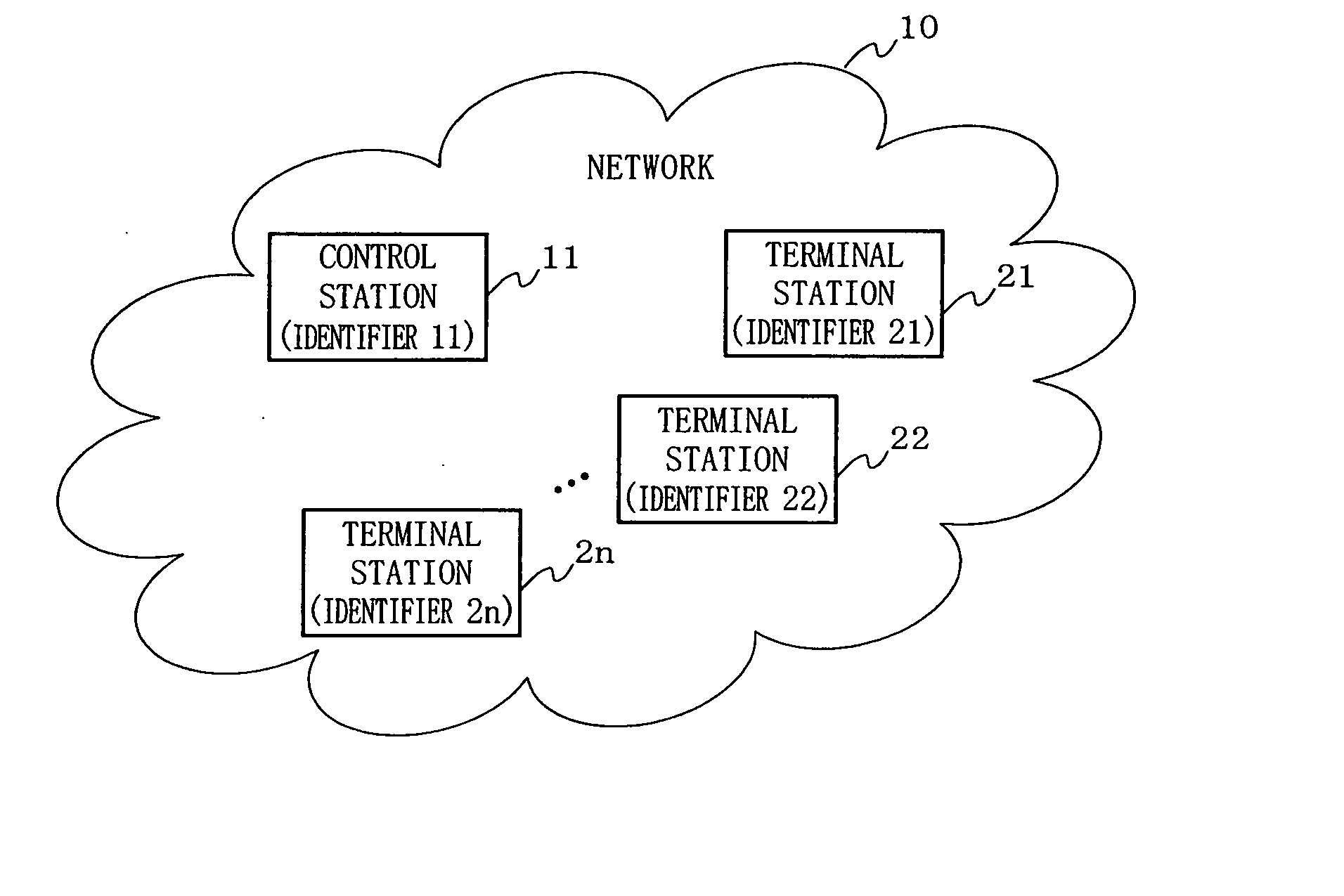
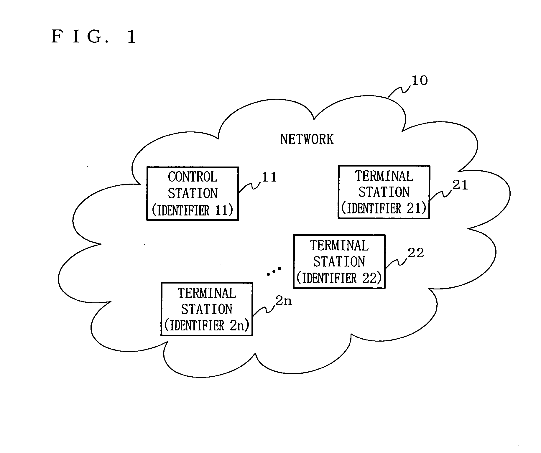
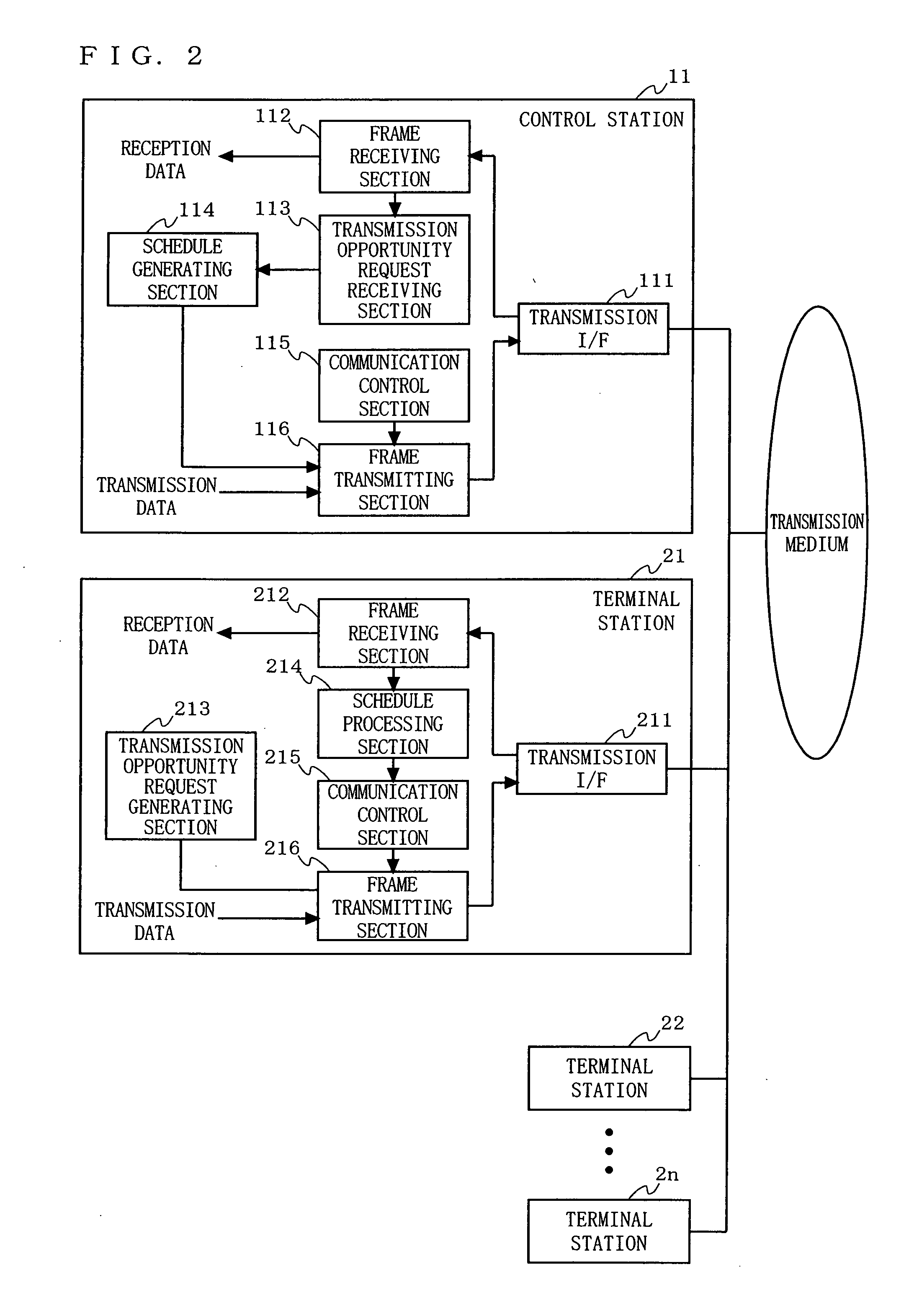
[0050]FIG. 2 is an illustration showing a detailed configuration of a medium access control system according to a first embodiment of the present invention. In FIG. 2, the control station 11 includes a transmission interface (I / F) 111, a frame receiving section 112, a transmission opportunity request receiving section 113, a schedule generating section 114, a communication control section 115, and a frame transmitting section 116. The terminal station 21 includes a transmission interface (I / F) 211, a frame receiving section 212, a transmission opportunity request generating section 213, a schedule processing section 214, a communication control section 215, and a frame transmitting section 216. The other terminal stations 22 through 2n each have a structure identical to that of the terminal station 21.

[0051] First, the structure of each of the control station 11 and the terminal stations 21 through 2n is schematically described below.

[0052] In the control station 11, the transmiss...

second embodiment

[0067]FIG. 18 is an illustration showing a detailed configuration of a medium access control system according to a second embodiment of the present invention. In FIG. 18, the control station 11 includes the transmission interface 111, the frame receiving section 112, the transmission opportunity request receiving section 113, the schedule generating section 114, the communication control section 115, the frame transmitting section 116, and a non-transmission detecting section 117. The terminal station 21 includes the transmission interface 211, the frame receiving section 212, the transmission opportunity request generating section 213, the schedule processing section 214, the communication control section 215, the frame transmitting section 216, and a non-transmission detecting section 217. The other terminal stations 22 through 2n each have a structure identical to that of the terminal station 21.

[0068] As illustrated in FIG. 18, the medium access control system according to the ...

third embodiment

[0072]FIG. 20 is an illustration showing a detailed configuration of a medium access control system according to a third embodiment of the present invention. In FIG. 20, the control station 11 includes the transmission interface 111, the frame receiving section 112, the transmission opportunity request receiving section 113, the schedule generating section 114, the communication control section 115, the frame transmitting section 116, a transmission-completed frame processing section 118, and a transmission-completed report generating section 119. The terminal station 21 includes the transmission interface 211, the frame receiving section 212, the transmission opportunity request generating section 213, the schedule processing section 214, the communication control section 215, the frame transmitting section 216, a transmission-completed frame processing section 218, and a transmission-completed report generating section 219. The other terminal stations 22 through 2n each have a str...


PUM


Abstract

A medium access control method is provided in which a control station transmits one specific frame to terminal stations, thereby arranging a schedule of a data transmission time of the control station and each of the terminal stations and allowing a time zone unused by a station for data transmission to be allocated to another station. The control station transmits a schedule frame having defined therein a time occupied by each of the terminal stations, thereby reducing overhead. Also, the completion of the preceding communication performed by another station is detected, thereby effectively using an idle time of a medium and improving transmission efficiency.

Description

[0001] This is a Rule 1.53(b) Divisional Application of Ser. No. 10 / 845,505, filed May 14, 2004, which is now allowed.BACKGROUND OF THE INVENTION [0002] 1. Field of the Invention [0003] The present invention relates to medium access control methods and systems. More specifically, the present invention relates to a medium access control method to be used in a network system including a plurality of terminals accessing each other for allowing a specific terminal (control station) to control access of all of the other terminals (terminal stations) in a time division manner, and a medium access control system using the method. [0004] 2. Description of the Background Art [0005] In order to achieve a communication network system including a control station for controlling access to a network and terminal stations for accessing the network under the control of the control station, various wireless LAN systems have been put into practical use. Examples of widely-available wireless LAN syste...

Claims


Application Information

Patent Timeline
Patent Type & Authority Applications(United States)
IPC IPC(8): H04B7/212H04L12/28
CPCH04L12/2803H04L12/2827H04L63/08H04L2012/2841H04W74/02H04W12/06H04W84/12H04W74/006H04L2012/2843H04L12/28H04L12/40H04L9/40
Inventor KURODA, GOUKUROBE, AKIOIKEDA, KOJIYOSHIZAWA, KENSUKE
Owner PANASONIC CORP
Why Eureka
Try Eureka