
Receiving method for receiving signals by a plurality of antennas, and a receiving apparatus and a radio apparatus using the same

a receiving method and antenna technology, applied in the field of receiving technology, can solve the problems of significant deterioration in the transmission quality of signals, increase in circuit scale, and increase in circuit cost, so as to improve the accuracy of phase rotation amount and enhance the accuracy of correcting phase error

Inactive Publication Date: 2008-03-13
HERA WIRELESS
View PDF17 Cites 57 Cited by
  • Summary
  • Abstract
  • Description
  • Claims
  • Application Information

AI Technical Summary

Benefits of technology

[0009] The present invention has been made in view of the foregoing circumstances and an advantage of the present invention is to provide a technology by which to correct phase errors contained in signals received respectively by a plurality of antennas. Another advantage of the present invention is to provide a receiving technology by which to correct the interantenna frequency offset error. Still another advantage of the present invention is to provide a receiving technology by which to correct frequency offsets contained among signals received by a plurality of antennas.
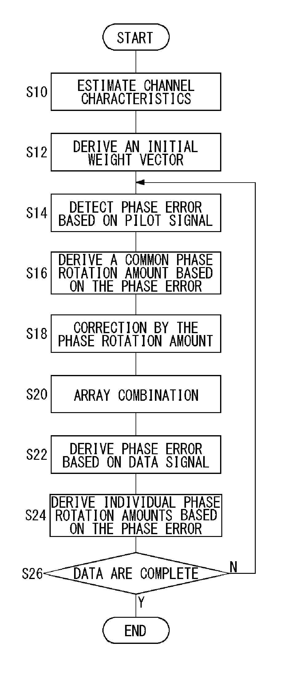
[0010] In order to resolve the above problems, a receiving apparatus according to one embodiment of the present invention comprises: a receiver which receives a plurality of multicarrier signals corresponding respectively to a plurality of antennas wherein a pilot signal is assigned to at least one subcarrier in the multicarrier signals; a derivation unit which derives amounts of phase rotation for the plurality of multicarrier signals received in the receiver, respectively; a rotation unit which rotates the phase of weight vectors to be multiplied by the plurality of multicarrier signals received in the receiver, by the amounts of phase rotation derived in the derivation unit; and a combining unit which weights respectively the plurality of multicarrier signals received in the receiver, with the weight vectors rotated by the rotation unit and which combines results of weightings. The combining unit determines the combined results, and the derivation unit includes: means for executing remodulation based on the results determined by the combining unit and a channel characteristic and deriving a first phase difference between the plurality of multicarrier signals received in the receiver and a result of the remodulation; means for executing remodulation based on a value of the pilot signal and the channel characteristic and deriving a second phase difference between the plurality of multicarrier signals received in the receiver and a result of the remodulation; and means for deriving an amount of phase rotation based on the first phase difference and the second phase difference.
[0011] According to this embodiment, the amount of phase rotation is derived based on a result where the pilot signal has been remodulated and a result where an array-synthesized result is remodulated. Hence, the accuracy of a phase rotation amount can be improved and the accuracy of correcting the phase error can be enhanced.
[0012] The multicarrier signal received by the receiver may be formed of a plurality of streams; the derivation unit may derive a common phase rotation amount over the streams; the weight vectors to be rotated in the rotation unit may correspond respectively to the plurality of streams; and the combining unit may perform weighting, combining and decision on the plurality of streams, respectively. In such a case, the processing according to the number of streams is performed and thus a plurality of streams can be dealt with.
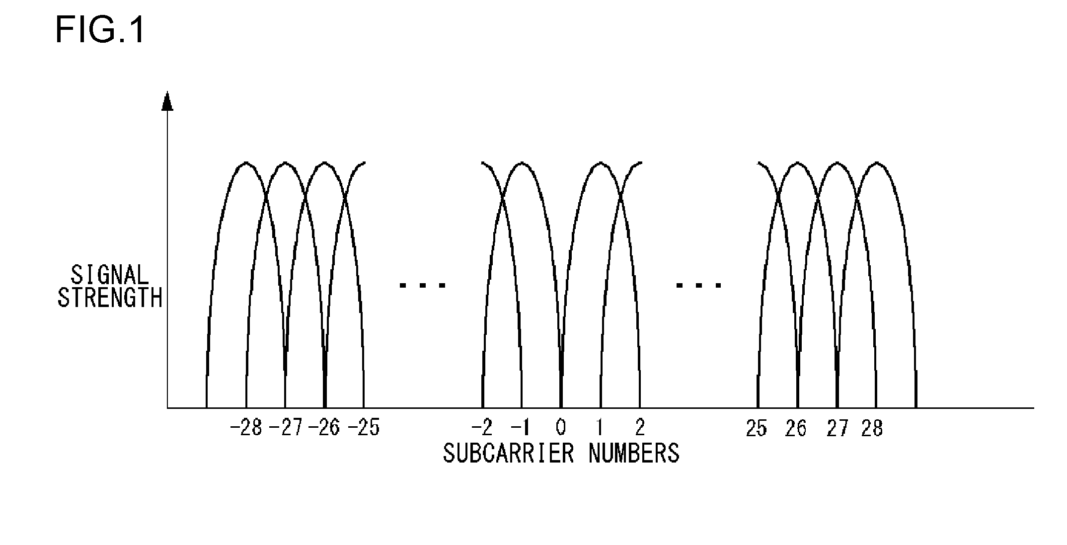
[0013] The derivation unit may derive the first phase difference by associating respectively with the plurality of subcarriers and derive the second phase difference by expanding a phase difference in a subcarrier to which the pilot signal is assigned, to the plurality of subcarriers. In such a case, two phase differences having different properties are derived, so that the phase errors whose occurrence causes differ can be corrected.
[0014] The derivation unit may derive the phase rotation amount, based on the second phase difference derived in a predetermined symbol and the first phase difference derived in a symbol before the symbol from which the second phase difference has been derived. In such a case, the derivation timing for two phase difference may differ, so that two phase differences can be derived by using different derivation methods.

Problems solved by technology

When an OFDM (Orthogonal Frequency Division Multiplex) modulation scheme is used, a combining gain drops due to such phase error and therefore the transmission quality of signals deteriorates significantly.
Also, the phase error differs on a subcarrier-by-subcarrier basis due to Doppler shift or frequency selective fading.
However, a method for adaptively updating the weight generally entails a rise in calculation amount, thus leading to an increase in circuit scale and a rise in circuit cost.

Method used


Image

  • Receiving method for receiving signals by a plurality of antennas, and a receiving apparatus and a radio apparatus using the same
  • Receiving method for receiving signals by a plurality of antennas, and a receiving apparatus and a radio apparatus using the same
  • Receiving method for receiving signals by a plurality of antennas, and a receiving apparatus and a radio apparatus using the same

Examples


second embodiment

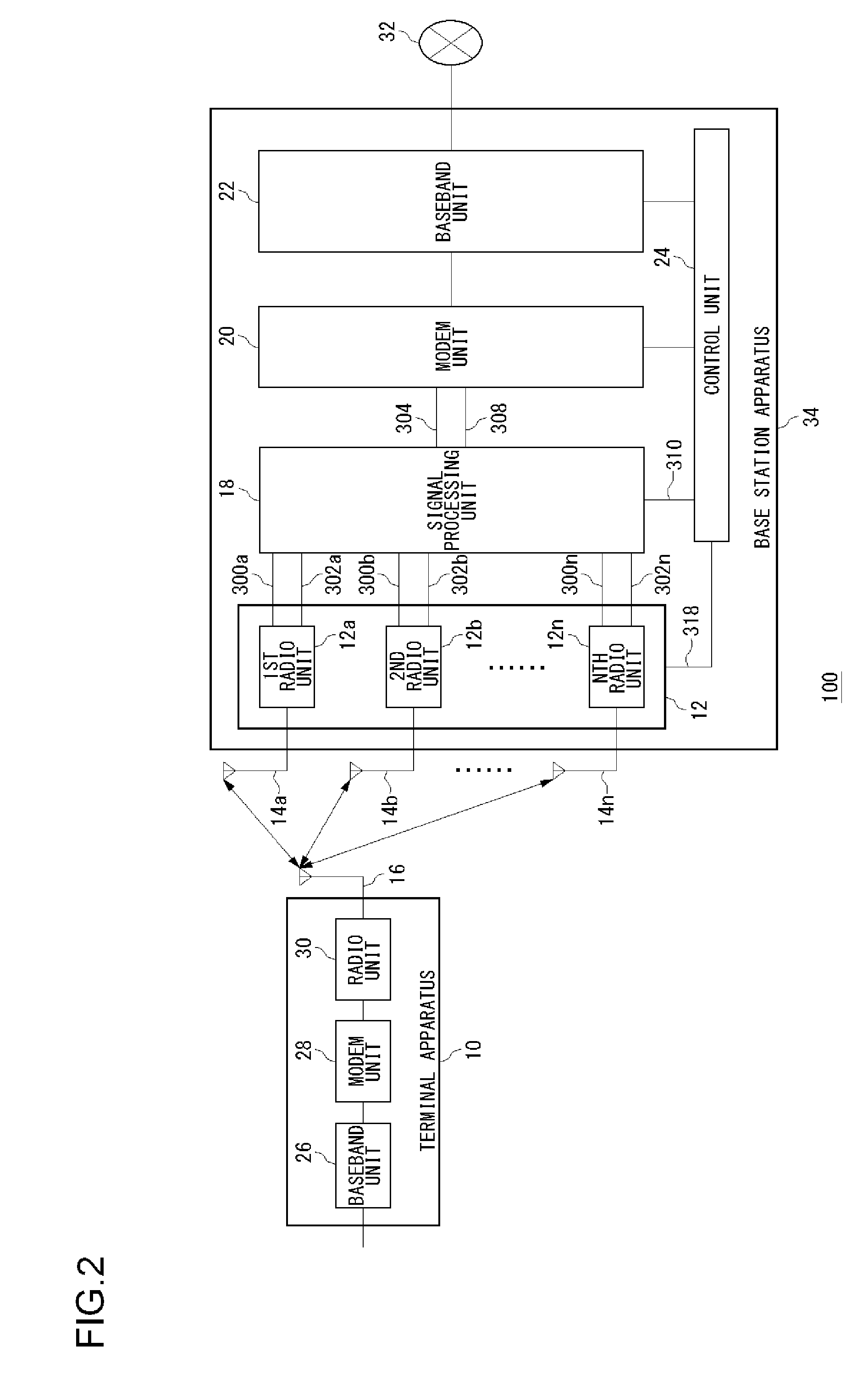
[0161] Before describing the present invention in detail, an outline of the present invention will be described first. Another exemplary embodiment of the present invention relates to a base station apparatus, to which a terminal apparatus is accessible, such as one used in a communication system like a wireless LAN (Local Area Network). An OFDM modulation scheme is used in the communication system. The base station apparatus according to the exemplary embodiment of the present invention is comprised of a plurality of antennas and local oscillators corresponding respectively to the plurality of antennas. The base station apparatus receives multicarrier signals received from a terminal apparatus to be communicated with, by a plurality of antennas, and the thus received multicarrier signals are subjected to quadrature detection by the local oscillator. Further, the base station apparatus computes weight factors from a plurality of quadrature-detected multicarriers, for each antenna an...

third embodiment

[0243] Before describing the present invention in detail, an outline of the present invention will be described first. Still another exemplary embodiment of the present invention relates to a base station apparatus, to which a terminal apparatus is accessible, such as one used in a communication system like a wireless LAN (Local Area Network). An OFDM modulation scheme is used in the communication system. The base station apparatus according to the exemplary embodiment of the present invention is comprised of a plurality of antennas and local oscillators corresponding respectively to the plurality of antennas. The base station apparatus receives multicarrier signals received from a terminal apparatus to be communicated with, by a plurality of antennas, and the thus received multicarrier signals are subjected to quadrature detection by the local oscillator. Further, the base station apparatus computes weight factors from a plurality of quadrature-detected multicarriers, for each ante...


PUM


Abstract

A weight vector computing unit derives amounts of phase rotation for a plurality of multicarrier signals, respectively, and rotates the phase of a weight vector. A combining unit weights respectively a plurality of multicarrier signals with the phase-rotated weight vector, combines weighting results, and determines a combined result. A receiving weight vector computing unit remodulates the determined result and derives a first phase difference between the plurality of multicarrier signals and a result of the remodulation. The receiving weight vector computing unit remodulates the values of pilot signals and derives a second phase difference between the plurality of multicarrier signals and a result of the remodulation. Further, the receiving weight vector derives phase rotation amounts based on the first phase difference and the second phase difference.

Description

CROSS-REFERENCE TO RELATED APPLICATIONS [0001] This application is based upon and claims the benefit of priority from the prior Japanese Patent Applications No. 2006-247292, filed Sep. 12, 2006, the prior Japanese Patent Application No. 2006-247293, filed Sep. 12, 2006 and the prior Japanese Patent Application No. 2006-284421, filed Oct. 18, 2006, the entire contents of which are incorporated herein by reference. BACKGROUND OF THE INVENTION [0002] 1. Field of the Invention [0003] The present invention relates to a receiving technology, and it particularly relates to a receiving method for receiving signals by a plurality of antennas and a receiving apparatus and a radio apparatus using said method. [0004] 2. Description of the Related Art [0005] In wireless communications, it is generally desired that the limited frequency resources be used effectively. One of the technologies that effectively utilize the frequency resources is adaptive array antenna technology. In the adaptive arra...

Claims


Application Information

Patent Timeline
IPC IPC(8): H04B3/10
CPCH04B7/084H04B7/0845H04L27/2657H04L27/2675H04L2027/0067H04L27/2613H04L2027/0061
Inventor NAKAO, SEIGOOTANI, YOSHIYUKIITO, KIYOSHIGE
Owner HERA WIRELESS
Learn More