Rolling Bearing Assembly

a bearing assembly and rolling bearing technology, applied in the direction of mechanical equipment, rigid support of the bearing unit, transportation and packaging, etc., can solve the problems of hub shafts not being able to achieve sufficient strength, the bearing assembly may not be able to bear the moment load, and the bearing assembly may not be able to obtain a sufficient rigidity as a whole, so as to achieve greater rigidity and increase the axial distance

Inactive Publication Date: 2008-03-13
JTEKT CORP
View PDF7 Cites 1 Cited by
  • Summary
  • Abstract
  • Description
  • Claims
  • Application Information

AI Technical Summary

Benefits of technology

[0010] In this case, the axle shaft inserted in the hub shaft is carried by the first spindle bearing and the second spindle bearing which define an increased axial distance therebetween. ...

Problems solved by technology

Unfortunately, however, the above rolling bearing assembly may not be able to obtain a sufficient rigidity as a whole because the rolling bearing assembly is used for assembling the hub shaft to the axle shaft.
When a ...

Method used


Image

  • Rolling Bearing Assembly
  • Rolling Bearing Assembly

Examples


Embodiment Construction

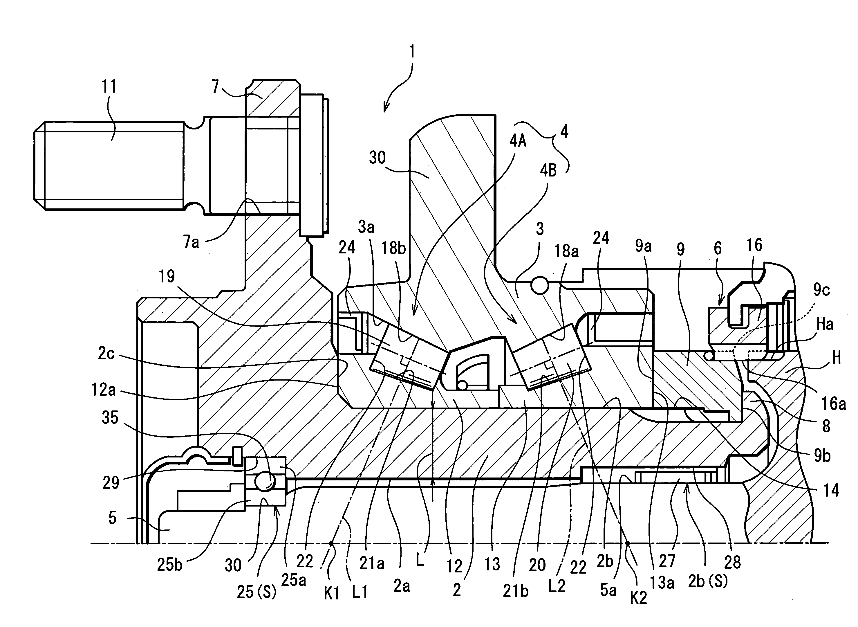
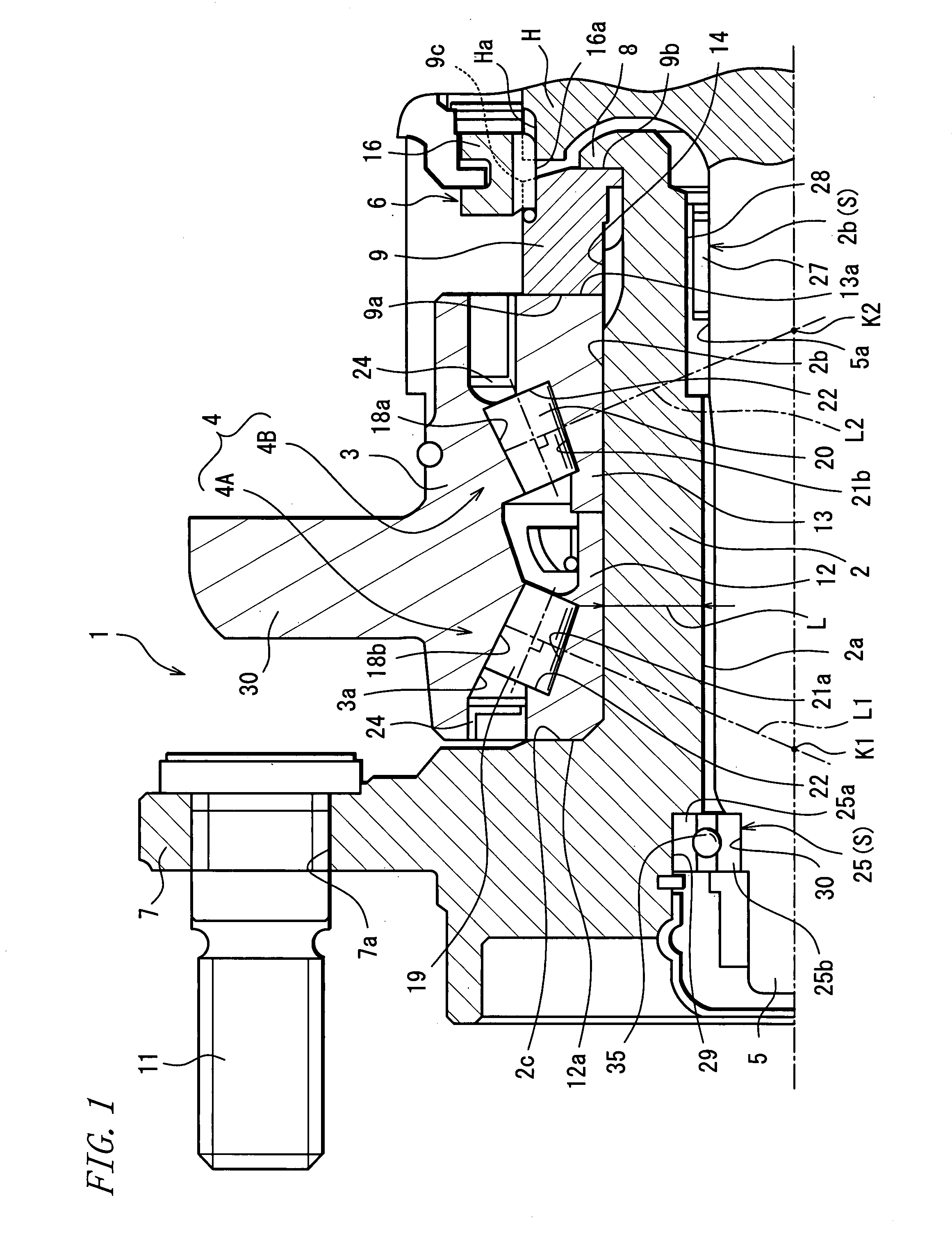
[0012] One embodiment of the invention will be described as below with reference to the accompanying drawing.

[0013] As shown in FIG. 1, a rolling bearing assembly 1 according to the embodiment includes: a hub shaft 2 substantially of a cylindrical shape; a double-row hub bearing 4 (tapered roller bearing) mounted on an outer periphery of the hub shaft 2; and a spindle bearing S interposed between an axle shaft 5 disposed in an inside surface of the hub shaft 2 and the hub shaft 2. The hub shaft 2 is mounted with a road wheel. An outer ring 3 of the hub bearing 4 is fixed to a suspension and the like by way of a flange 30 integrally formed with the outer ring 3. An axis of the hub shaft 2 is aligned with an axis of the axle shaft 5.

[0014] The hub shaft 2 is integrally formed with a flange 7 for mounting the road wheel at one end thereof, which is on an outer side with respect to a vehicle (the left-hand side as seen in FIG. 1 and hereinafter, simply referred to as the outer side, a...


PUM


Abstract

A rolling bearing assembly 1 includes: a hub shaft 2; a double-row hub bearing 4 disposed on an outer periphery of the hub shaft 2 and possessing first-row rolling elements 19 on an outer side and second-row rolling elements 20 on an inner side; and a spindle bearing S interposed between an axle shaft 5 and the hub shaft 2. The spindle bearing S is located at place outside a range defined between working points K1, k2 of the first-row and second-row rolling elements 19, 20 of the hub bearing 4 with respect to an axial direction of the hub shaft, whereby the whole body of the rolling bearing assembly 1 is increased in rigidity. Thus, the rolling bearing assembly is increased in rigidity as a whole, so as to be able to easily bear a moment load particularly applied to the hub shaft, as well as to ensure the strength of the hub shaft.

Description

TECHNICAL FIELD [0001] The present invention relates to a rolling bearing assembly principally used in an automotive freewheel hub or the like. BACKGROUND ART [0002] A freewheel hub for use in part-time 4WD vehicles adapted for shifting between a 2WD drive mode and a 4WD drive mode, for example, is known as a hub adapted for on / off transmission of a driving force transferred thereto. In a case where the freewheel hub is used, the following merit is offered. Two road wheels serving as driven wheels during travel in the 2WD drive mode do not require the rotation of a driving system (axle shaft, differentials, propeller shaft and the like) and hence, the vehicle may achieve improved fuel efficiency, decreased vibrations and noises, increased durability of driving components, and the like. [0003] The above freewheel hub is provided with a rolling bearing assembly. A rolling bearing assembly disclosed in Japanese Examined Patent Publication No. 2003-507683, for example, includes: a hub s...

Claims


Application Information

Patent Timeline
IPC IPC(8): F16C19/38F16C35/04
CPCF16C19/386B60B27/06F16C35/12F16C19/54F16C2326/02B60B35/00B60B35/18
Inventor DEGUCHI, MASARUTSUZAKI, YOUICHITAKEDA, YOSHISHIGE
Owner JTEKT CORP
Why Eureka
Try Eureka