Spinal plate system for stabilizing a portion of a spine

a spine and plate technology, applied in the field of compression plate, can solve the problems of destabilizing a spinal column, degeneration of the intervertebral disc, pain and/or nerve damage, etc., and achieve the effect of reducing concerns about positioning and/or dropping retainers, reducing the risk of fracture, and minimizing the damage of adjacent tissu

Inactive Publication Date: 2008-03-13
ABBOTT LAB INC +1
View PDF32 Cites 69 Cited by
  • Summary
  • Abstract
  • Description
  • Claims
  • Application Information

AI Technical Summary

Benefits of technology

[0015] In some embodiments, a spinal compression plate may compress longitudinally during use; however, the spinal compression plate may be inhibited from expanding longitudinally during use. A movement mechanism may inhibit expansion during use. In some embodiments, a movement mechanism may include one or more protrusions on the spinal compression plate. Protrusions may be positioned on surfaces of the plates that normally contact each other. Some embodiments include a protrusion on a first plate that engages one or more protrusions (e.g., serrations) on a second plate to maintain a distance between the vertebrae after compression. In some embodiments, at least a portion of a serrated surface of a movement mechanism may be curved to increase an area of the movement mechanism and thus enhance stability of a spinal compression plate.
[0018] In some embodiments, a spinal compression plate may freely compress and expand unencumbered by a movement mechanism. In some embodiments, a first plate may not include protrusions to engage protrusions on a second plate. In an embodiment, a second plate may not have protrusions to engage protrusions on a first plate. Compression and expansion of a spinal compression plate may allow the plate to accommodate natural vertebral movement. A coupling cavity may restrict the range of motion of a first plate relative to a second plate of a spinal compression plate and / or inhibit separation of the first plate from the second plate. In some embodiments, portions of the first plate that engage the second plate and / or portions of the second plate that engage the first plate, may be textured to alter frictional properties of the first plate relative to the second plate.
[0023] In some spinal plate system embodiments, a portion of a plate forms a wall of an opening. A recess may be positioned in a wall to engage a retainer that inhibits removal of a fastener from a plate. A recess may be biased to allow the fastener to enter a vertebra at a desired angle. Allowing a fastener to enter a spinal compression plate at an angle may facilitate establishment of a secure connection between the spinal compression plate and the vertebra. A recess may have a larger height than a height of the portion of a retainer that fits within the recess. The greater height of the recess may allow for some angulation adjustment of a fastener positioned through the retainer into a vertebra. In some embodiments, openings on a superior end of a spinal compression plate may allow for greater angulation of fasteners than openings on an inferior end of the spinal compression plate.
[0027] A retainer may have a gap that allows the retainer to radially expand and / or contract. A retainer may engage a fastener to inhibit backout of the fastener from a plate. Engaging a retainer with a fastener may inhibit a fastener head from rising above an upper, surface of the plate even if the fastener loosens in the bone. Retaining a fastener below the upper surface of a plate may inhibit contact of adjacent tissue with the fastener and / or fastener head during use. Damage of adjacent tissue may be minimized or eliminated by inhibiting contact of adjacent tissue with the fastener and / or fastener head during use.
[0028] In some embodiments, a retainer may be positioned in an opening of a spinal compression plate prior to surgical insertion of the compression plate in a patient. A spinal compression plate may be positioned adjacent to a portion of the spine that requires spinal fixation. Holes may be drilled, tapped, and / or otherwise formed in a portion of a vertebra underlying each opening. Fasteners may be inserted through the openings and into the holes. Fastener heads may be positioned in the openings so that retainers surround at least a portion of the fastener heads. Advantageously, a fastener may be held within the opening by a retainer. A spinal compression plate with a pre-positioned retainer may reduce concerns about positioning and / or dropping retainers during surgery.

Problems solved by technology

An intervertebral disc may be subject to degeneration caused by trauma, disease, and / or aging.
Partial or full removal of an intervertebral disc may destabilize a spinal column.
Excessive pressure applied to the nerves may cause pain and / or nerve damage.
Fastening systems may attach a spinal plate to vertebrae without allowing fasteners of the fastening systems to back out from the vertebrae.
In some embodiments, a spinal compression plate may compress longitudinally during use; however, the spinal compression plate may be inhibited from expanding longitudinally during use.

Method used


Image

  • Spinal plate system for stabilizing a portion of a spine
  • Spinal plate system for stabilizing a portion of a spine
  • Spinal plate system for stabilizing a portion of a spine

Examples


Embodiment Construction

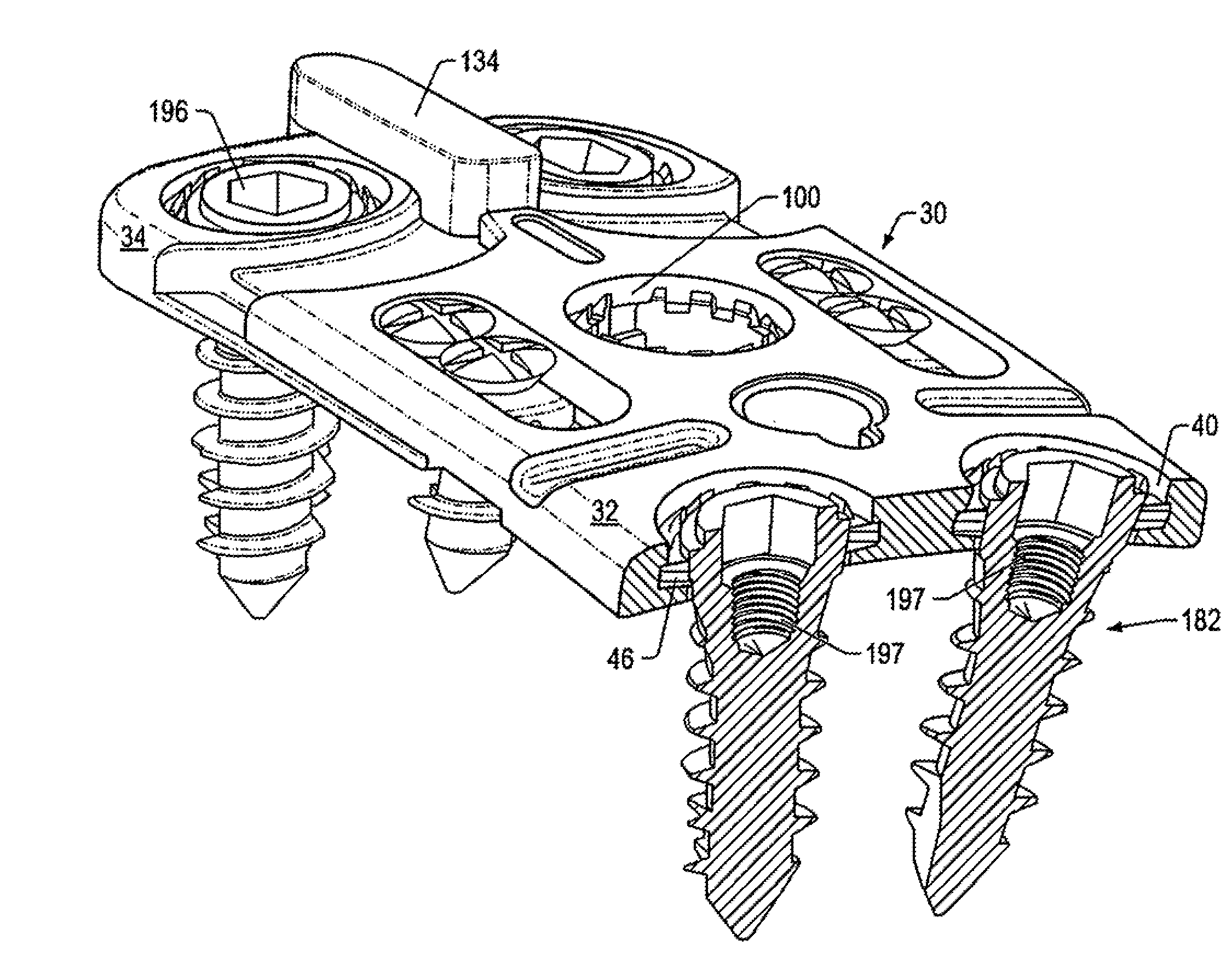
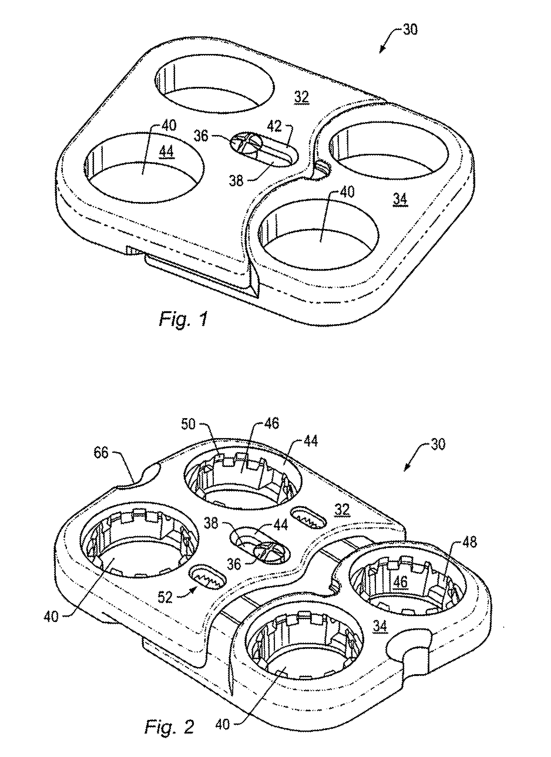
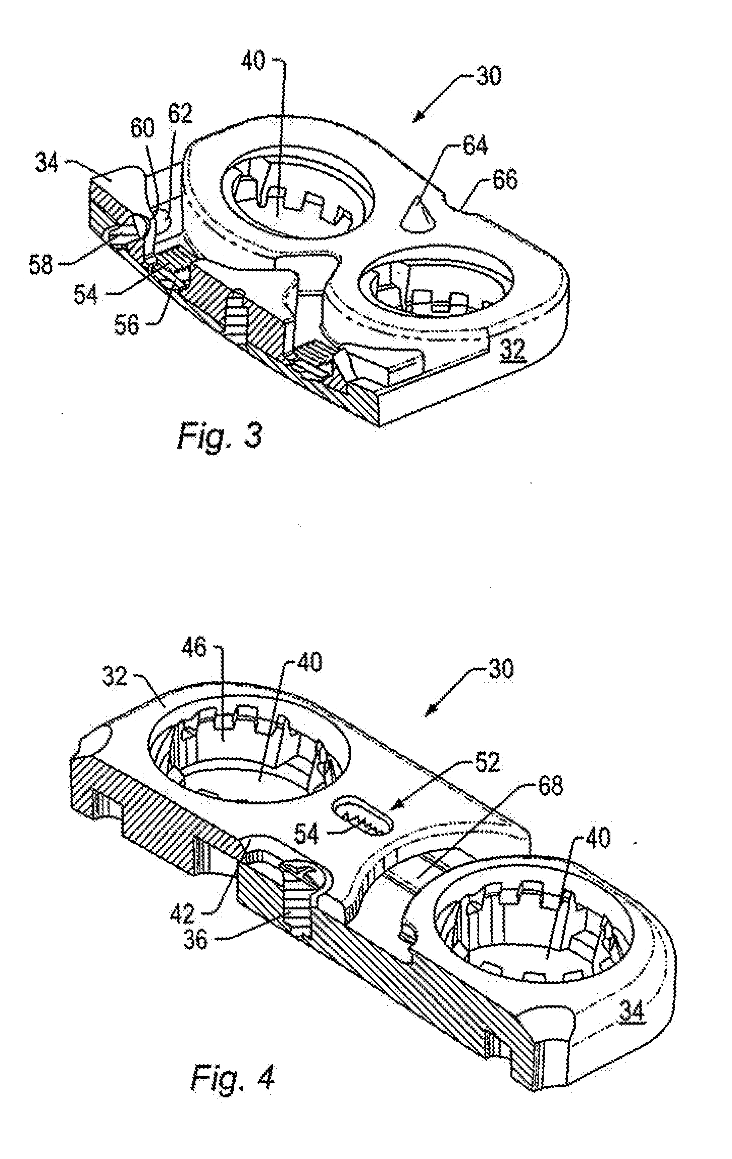
[0061] A spinal plate system may be used to stabilize a portion of a spine. A spinal plate system may include a spinal compression plate and fasteners that couple the spinal compression plate to vertebrae. Components of a spinal plate system may include materials such as, but not limited to, stainless steel, titanium, titanium alloys, ceramics, and / or polymers. Some components of a spinal plate system may be made of materials that may be autoclaved and / or chemically sterilized. Some components of a spinal plate system may be formed of materials unable to be autoclaved and / or chemically sterilized. Components unable to be autoclaved and / or chemically sterilized may be made of sterile materials and placed in working relation to other sterile components during assembly of a spinal plate system.

[0062] Spinal plate systems may typically be used to correct problems in lumbar and cervical portions of a spine resulting from injury and / or disease. For example, a spinal plate system may be i...


PUM


Abstract

A spinal plate system that maintains intervertebral spacing and spinal stability is provided. In an embodiment, a spinal compression plate may include two or more plates coupled together form an adjustable-length plate. Compression of a spinal compression plate movement may mimic natural settling of bones in a spine and / or distribute at least a portion of a vertebral load to an implant positioned between two vertebrae. Maintaining at least a portion of the vertebral load on an insert may increase bone growth and increase fusion between an implant and surrounding vertebrae.

Description

PRIORITY CLAIM [0001] This application claims priority to Provisional Patent Application No. 60 / 353,272 entitled “SPINAL PLATE SYSTEM FOR STABILIZING A PORTION OF A SPINE” filed on Feb. 1, 2002.BACKGROUND OF THE INVENTION [0002] 1. Field of the Invention [0003] The present invention generally relates to bone fixation systems. An embodiment of the invention relates to a compression plate for a spinal fixation system. The compression plate may be installed using an anterior procedure. The compression plate may be used in conjunction with one or more spinal implants that fuse vertebrae together. [0004] 2. Description of Related Art [0005] An intervertebral disc may be subject to degeneration caused by trauma, disease, and / or aging. A degenerated intervertebral disc may have to be partially or fully removed from a spinal column. Partial or full removal of an intervertebral disc may destabilize a spinal column. Destabilization of a spinal column may alter a natural separation distance be...

Claims


Application Information

Patent Timeline
Patent Type & Authority Applications(United States)
IPC IPC(8): A61B17/58A61B17/56A61B17/00A61B17/17A61B17/70A61B17/80A61B17/86A61B17/88A61B17/92A61B19/00
CPCA61B17/1728A61B2019/446A61B17/1757A61B17/7059A61B17/8009A61B17/8023A61B17/8047A61B17/808A61B17/8085A61B17/809A61B17/8625A61B17/8888A61B17/8894A61B2017/00469A61B2017/00473A61B2017/00858A61B2017/922A61B2019/444A61B17/1735A61B90/92A61B90/94
Inventor FREID, JAMES M.WAGNER, ERIKAGRICOLA, JON P.VACCARO, ALEXANDER
Owner ABBOTT LAB INC
Why Eureka
Try Eureka