
Technique for supporting finding of location of cause of failure occurrence

a technology for locating a cause and a failure occurrence, which is applied in the direction of redundant hardware error correction, error detection/correction, instruments, etc., can solve the problems of large-scale and complicated recent information systems, and may have been required for an extended time,

Inactive Publication Date: 2008-03-13
IBM CORP
View PDF4 Cites 66 Cited by
  • Summary
  • Abstract
  • Description
  • Claims
  • Application Information

AI Technical Summary

Benefits of technology

[0006]Further, since the technique in JP '331 employs an approach as its base such that at first, a broad range is defined for an area to be investigated, and the range is then gradually narrowed down, a large number of experts might eventually participate in the investigation. Furthermore, the technique described in JP '331 indicates a range within which the cause of a failure is to be investigated, and it cannot indicate, after the range is determined, in what order the range is to be investigated. Thus, the investigation may not be performed efficiently.
[0007]Therefore, an object of the present invention is to provide a support system, a support method and a support program that can solve the above described problems. This object can be achieved by the combinations of the features described in the independent claims. Further, the dependent claims define useful embodiments of the invention.
[0008]To achieve the above-described object, there is provided, according to one aspect of the present invention, a support syste

Problems solved by technology

Recent information systems are large-scaled and complicated, and when a failure occurs, it is sometimes difficult to find a location of a cause of a failure occurrence.
However, in a large, complicated information system, a component in which an occurrence of a failure is reported and a component in which a root cause of the failure exists are frequently different from each other.
In this manner, before a cause of the failure has been found, a large number of subject matter experts may have been requested to perform investigations and an extended time may have been required.
However, since continuous operations are required in most cases for recent information systems, the system is immediately restarted following the occurrence of a failure, so that the system may already operate normally before a search is begun to locate a cause of a failure.
Therefore, it is frequently not practical for a current operating state to be employed in the analysis of the failures And in this case, the only data that can be employed while searching for the cause of a failure are those that were collected in the past, such as data previously entered in a log of events.
Furthermore, the technique described in JP '331 indicates a range within which the cause of a failure is to be investigated, and it cannot indicate, after the range is determined, in what order the range is to be investigated.
Thus, the investigation may not be performed efficiently.

Method used


Image

  • Technique for supporting finding of location of cause of failure occurrence
  • Technique for supporting finding of location of cause of failure occurrence
  • Technique for supporting finding of location of cause of failure occurrence

Examples


Embodiment Construction

[0020]The present invention will be described by referring to the best mode (hereinafter referred to as an embodiment) for carrying out this invention. However, the present invention as claimed in the appended claims is not limited to the embodiment, and not all the combinations of features explained in the following embodiment are always necessary as means for solving the problems.

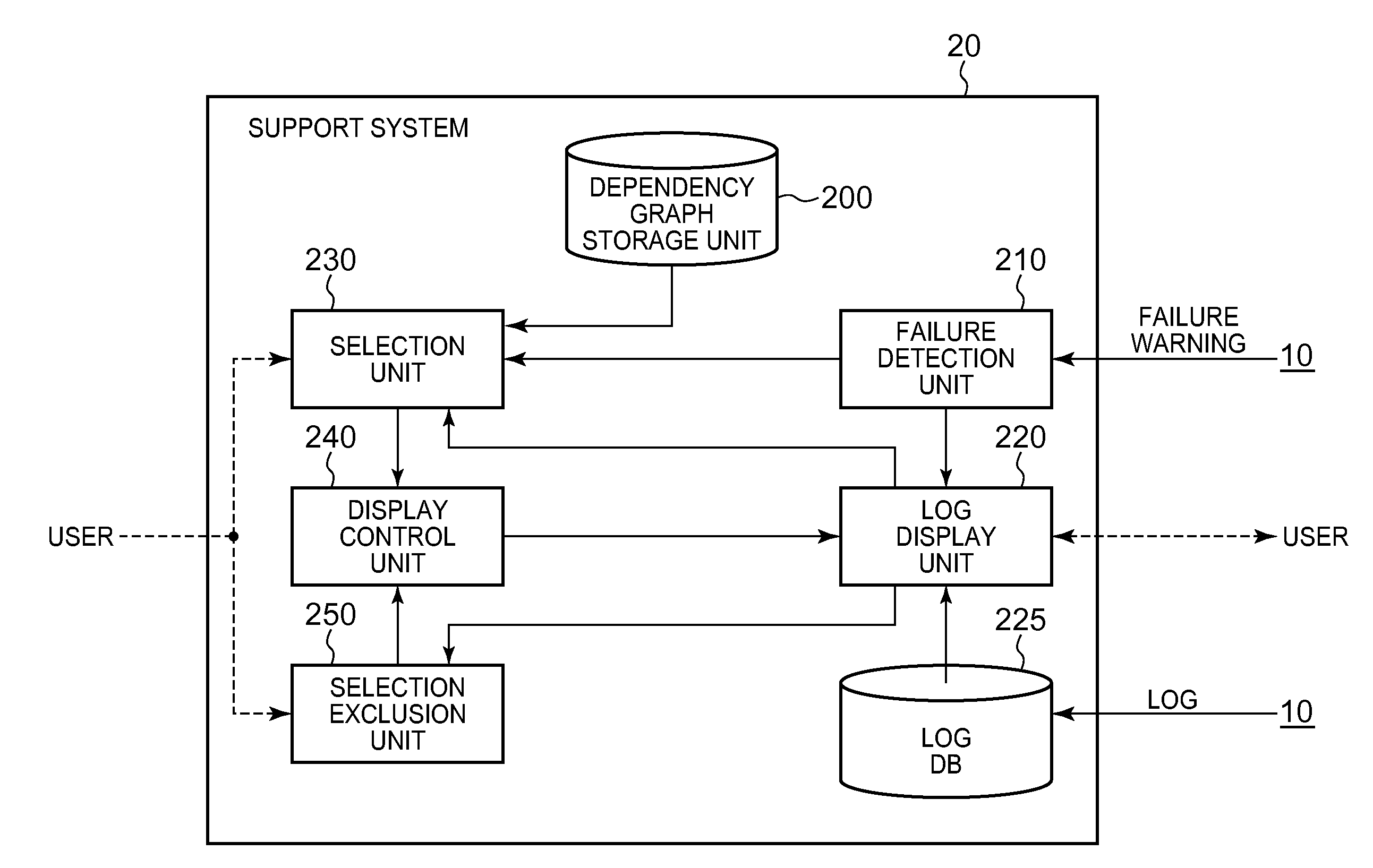
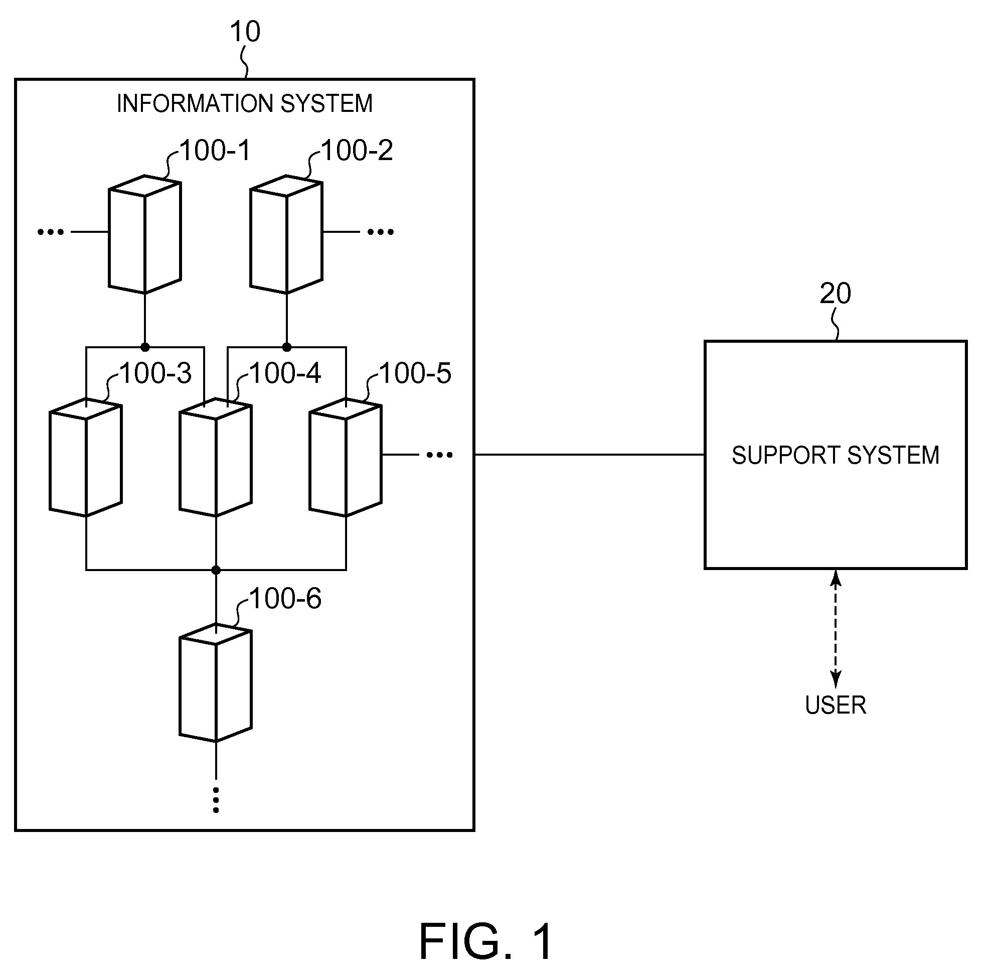
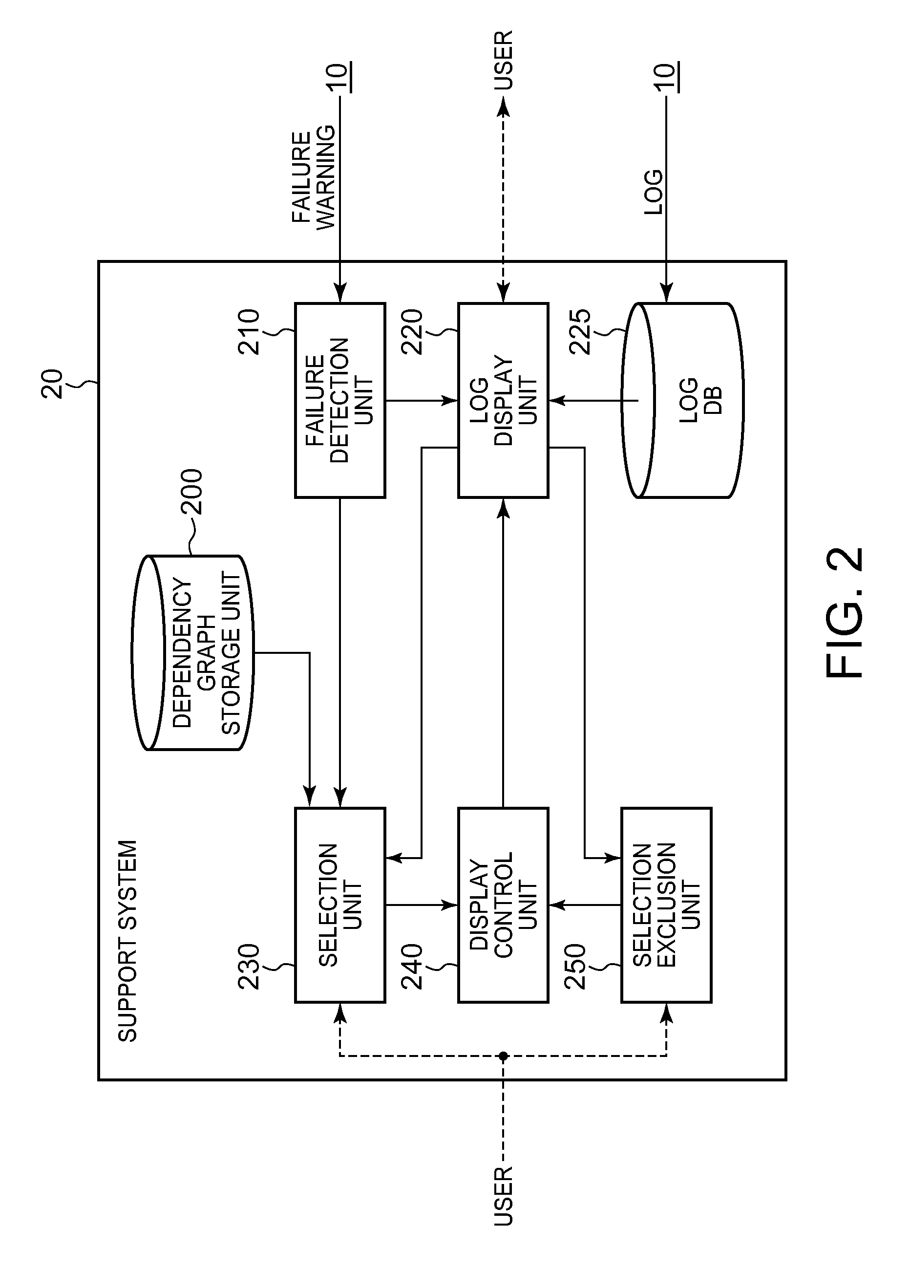
[0021]FIG. 1 shows the connection relationship of an information system 10 and a support system 20. The information system 10 includes a plurality of information processing units, e.g., information processing units 100-1 to 100-6. Each of the information processing units 100-1 to 100-6 includes hardware components and software components. The information processing units 100-1 to 100-6 are connected by telecommunication lines to mutually communicate with each other and perform processing. Each of the information processing units 100-1 to 100-6 may be a logical information processing unit that is arranged ...


PUM


Abstract

A support system includes a storage unit for storing a dependency graph in which components are expressed as nodes and relationships of components depending directly on each other are expressed with links, a log display unit for displaying, in response to detection of a failing component, a log of events occurring in the component, a selection unit for selecting, in response to an instruction by a user, a component that is adjacent to the failing component on the dependency graph, as a candidate component for a failure cause, and a display control unit for enabling the log display unit to additionally display a log of events occurring in the selected candidate component, wherein the selection unit further selects, in response to an instruction by a user, a component that is adjacent to the candidate component on the dependency graph as a new candidate component on condition that a log thereof has not yet been displayed.

Description

FIELD OF THE INVENTION[0001]The present invention relates to a technique for supporting finding of a location of a cause of a failure occurrence. Particularly, the present invention relates to a technique for supporting finding of a component that causes a failure occurrence in an information system comprising a plurality of components.BACKGROUND ART[0002]Recent information systems are large-scaled and complicated, and when a failure occurs, it is sometimes difficult to find a location of a cause of a failure occurrence. For example, the problem determination for finding a location of a failure cause depends largely on experienced knowledge and trial and error by subject matter experts (SME). As one of approaches of the problem determination by subject matter experts, an analysis of a log of events is performed. The analysis of the log of events is carried out, for example, by carefully investigating a log of events of a component for which a failure is reported, and by checking the...

Claims


Application Information

Patent Timeline
IPC IPC(8): G06F11/20G06F3/048
CPCG06F11/0709G06F11/328G06F11/20G06F11/079
Inventor SUZUKI, YASHUHIROGOTO, YASHUHISA
Owner IBM CORP
Learn More