
Hardware definition language generation for frame-based processing

a technology of frame-based processing and definition language, which is applied in the direction of instrumentation, program control, cad circuit design, etc., can solve the problems of not being so easily parallelizable and the size of target hardware, and achieve the effect of being easily parallelizable and parallelizabl

Active Publication Date: 2008-03-13
THE MATHWORKS INC
View PDF13 Cites 18 Cited by
  • Summary
  • Abstract
  • Description
  • Claims
  • Application Information

AI Technical Summary

Benefits of technology

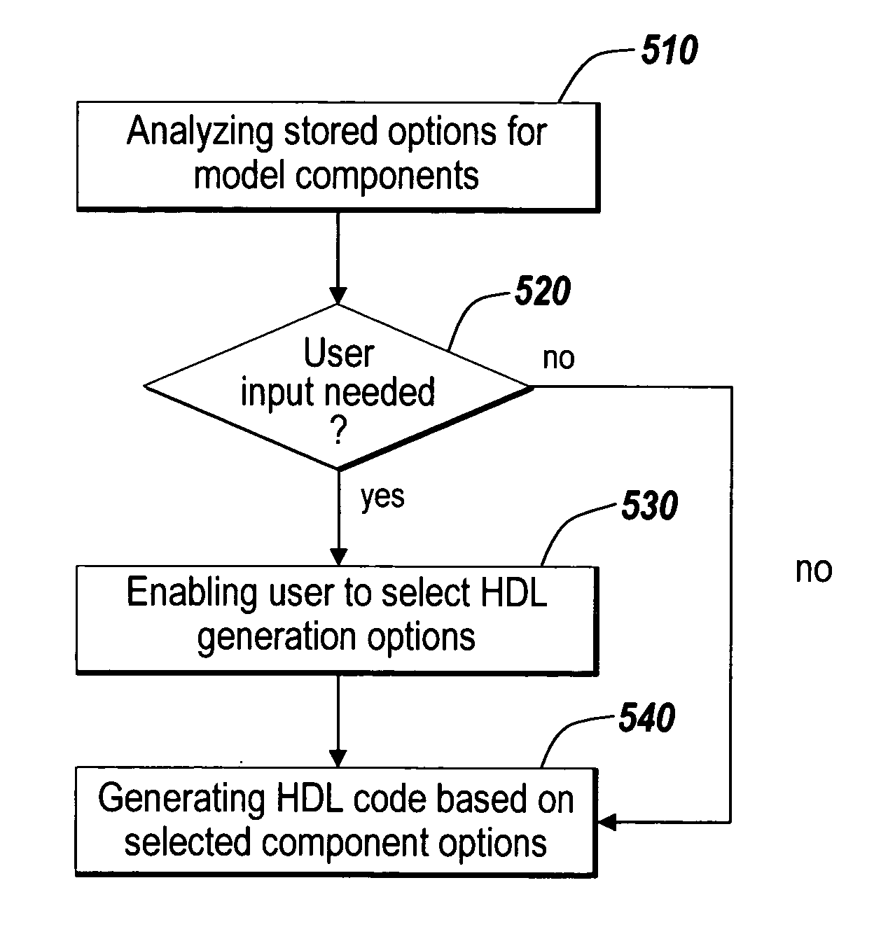
[0014]In one embodiment, a block diagram designer or a modeling environment user may be asked to select among options for HDL generation for frame-enabled blocks. Such options may include preferences directed to the size of target hardware or desired processing latency. For example, the user may specify to minimize the size of the proposed hardware (as described by the HDL representation), in which case the code generated for a frame-capable block may include only one copy of the function of the block and a buffer for holding all necessary elements of the input frame. Alternatively, a user may specify to improve the latency of the operation of the target device, which may come at the cost of the size of the target hardware. In case of such a choice, more than one element performing the same function may be generated, each element accepting and processing a portion of the frame input.
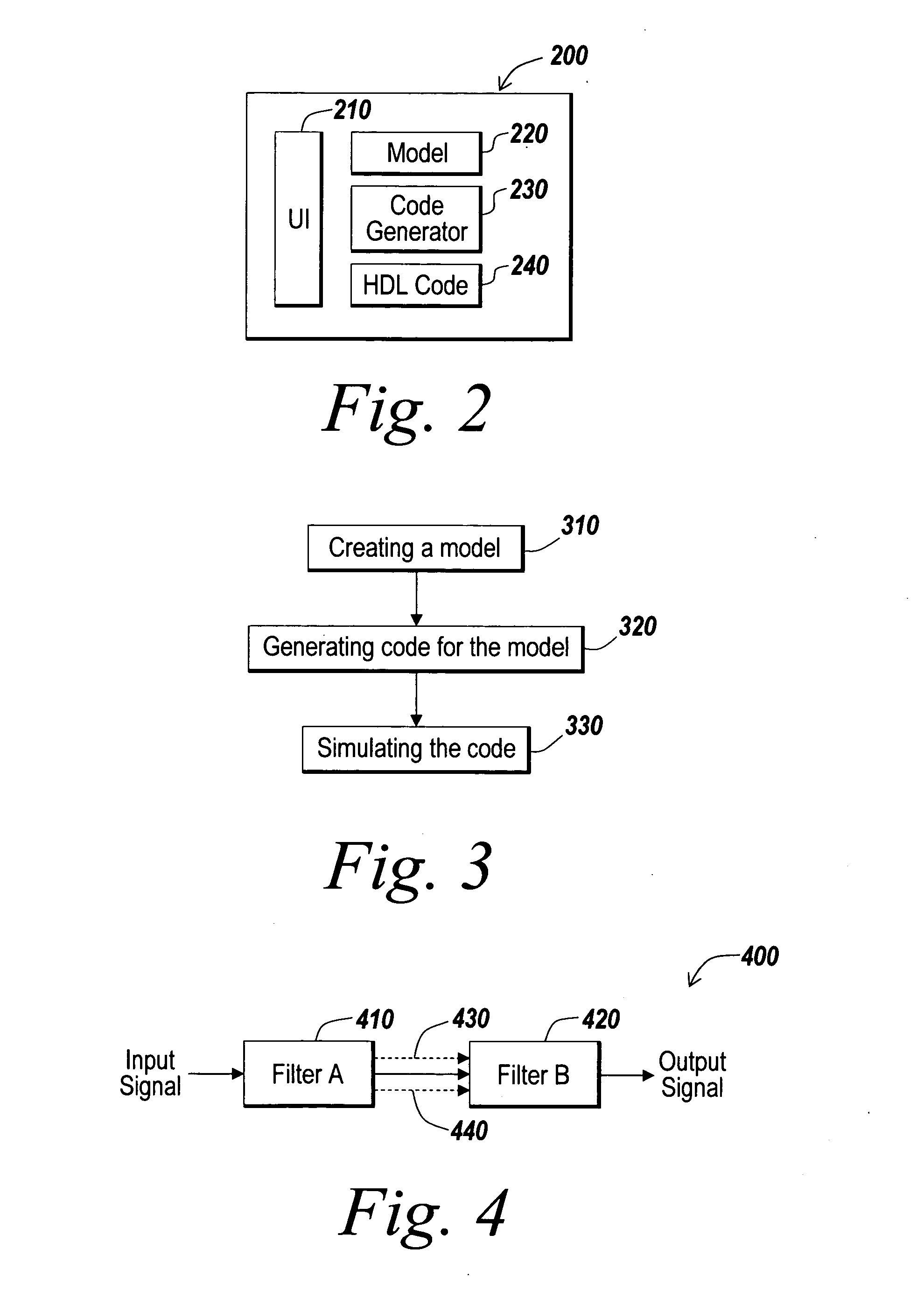
[0016]In yet another embodiment, the HDL representation generation mechanism may perform a block-per-block analysis to determine the best option for describing frame-like behavior in HDL. Some blocks may be easily parallelizable, such that their operation may be replicated in hardware, while other blocks may not be so easily parallelizable and may require a buffer storing input data while data is being processed on an individual basis.

Problems solved by technology

Alternatively, a user may specify to improve the latency of the operation of the target device, which may come at the cost of the size of the target hardware.
Some blocks may be easily parallelizable, such that their operation may be replicated in hardware, while other blocks may not be so easily parallelizable and may require a buffer storing input data while data is being processed on an individual basis.

Method used


Image

  • Hardware definition language generation for frame-based processing
  • Hardware definition language generation for frame-based processing
  • Hardware definition language generation for frame-based processing

Examples


Embodiment Construction

[0028]The illustrative embodiment of the present invention provides for automatic code generation from a model containing one or more blocks adapted for frame-based processing. The illustrative embodiment automatically generates code for the hardware description of the model, including the blocks adapted for frame-based processing. The hardware description may be generated in a Hardware Description Language (HDL), such as a very high speed integrated circuit hardware description language (VHDL), Verilog, and other similar languages. Although the illustrative embodiment is described herein relative to HDL code, one of skill in the art will appreciate that the hardware description may be generated in other languages, including programming languages, such as C++, C, C#, SystemC, Java and Javascript. Similarly, although the illustrative embodiment is directed to generating hardware description language code from Simulink® and / or MATLAB® models, one of skill in the art will appreciate th...


PUM


Abstract

An automatic code generation application is used to automatically generate code and build programs from a textual model or graphical model for implementation on the computational platform based on the design. One or more model elements may be capable of frame-based data processing. Various options and optimizations are used to generate Hardware Description Language (HDL) code for the frame-based model elements.

Description

BACKGROUND OF THE INVENTION[0001]The MATLAB® modeling environment is a product of The MathWorks, Inc. of Natick, Mass., which provides engineers, scientists, mathematicians, educators and other professionals across a diverse range of industries with an environment for technical computing applications. The MATLAB® programming language is an intuitive high performance language and technical computing environment that provides mathematical and graphical tools for mathematical computation, data analysis, visualization and algorithm development. MATLAB® is used to solve and / or understand complex engineering and scientific problems by developing mathematical models that simulate the problem. A model is prototyped, tested and analyzed by running the model under multiple boundary conditions, data parameters, or just a number of initial guesses.[0002]Besides using a textual modeling environment, such as the MATLAB® modeling environment or SystemC, a user may use graphical modeling environmen...

Claims


Application Information

Patent Timeline
Patent Type & Authority Applications(United States)
IPC IPC(8): G06F17/50
CPCG06F17/5045G06F30/30
Inventor OGILVIE, BRIAN K.MOSTERMAN, PIETER J.
Owner THE MATHWORKS INC
Learn More