Setting stones in the surface of electroformed piece

a technology of electroforming and electroforming pieces, which is applied in the direction of metal working devices, jewelry, apparel, etc., can solve the problems of extract extra sparkle, time-consuming and labor-intensive, and not being able to produce extra sparkle to bounce back at the viewer

Inactive Publication Date: 2008-03-20
K & M JEWELRY
View PDF1 Cites 34 Cited by
  • Summary
  • Abstract
  • Description
  • Claims
  • Application Information

AI Technical Summary

Benefits of technology

[0012]For achieving the above mentioned object, this method preferably comprises the following steps: A stone is put in the particularly designed inlay position of the wax mandrel which has been pre-painted with a layer of conductive coating. By utilizing different shapes and dimensions of the inlay position, the stone is put in the wax mandrel handily and firmly to ensure the stone does not fall off during electroforming process. The electroforming process will deposit metal layer by layer on the conductive coating, thereby filling the gap between the stone and the inlay position which holds the stone firmly in position. Therefore, the setting effect is achieved.
[0013]The inlay technique of the stone on the metal piece and the special arrangement of electroforming process further assist the inlay.

Problems solved by technology

(a) Its mandrel is comprised of tin metal so that it is not easy to be produced and to be extracted.
(b) Two copper protective coatings and one thin gold layer should be additionally plated on the tin mandrel; thus its process is time-consuming, not economical and not simplified.
(c) To enable the gold electroforming to reach the space between the stone and seat bottom, some passages are provided perpendicular to each seat. Therefore, it creates difficulty in a tiny electroformed piece. Moreover, the seat of the stone is closed for light to enter the stone backward and thus cannot produce extra sparkle to bounce back at the viewer.
(d) The stone setting effect is monotonous; does not have channel setting, bezel setting.

Method used


Image

  • Setting stones in the surface of electroformed piece
  • Setting stones in the surface of electroformed piece
  • Setting stones in the surface of electroformed piece

Examples


Embodiment Construction

[0026]In the following description, the metal used for electroforming is karat gold alloy or pure silver. The stone includes, but is not limited to, diamonds, synthetic stones, semi-precious stones or precious stones. The electroformed piece includes, but is not limited to, rings, earrings, bracelets, bangles, necklaces, pendants and brooches.

[0027]Basically, the specified inlay position design is divided into bottom layer (seat) design and surface layer design.

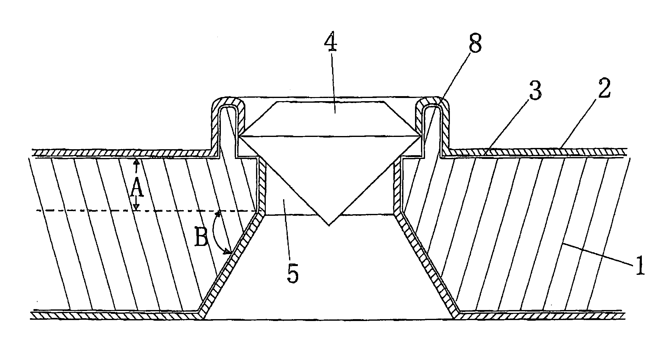
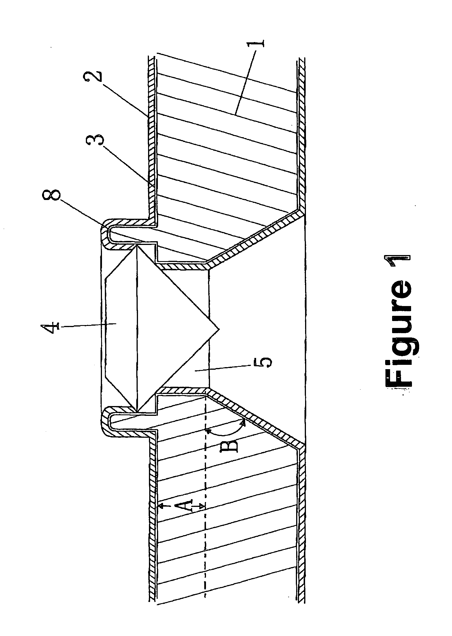
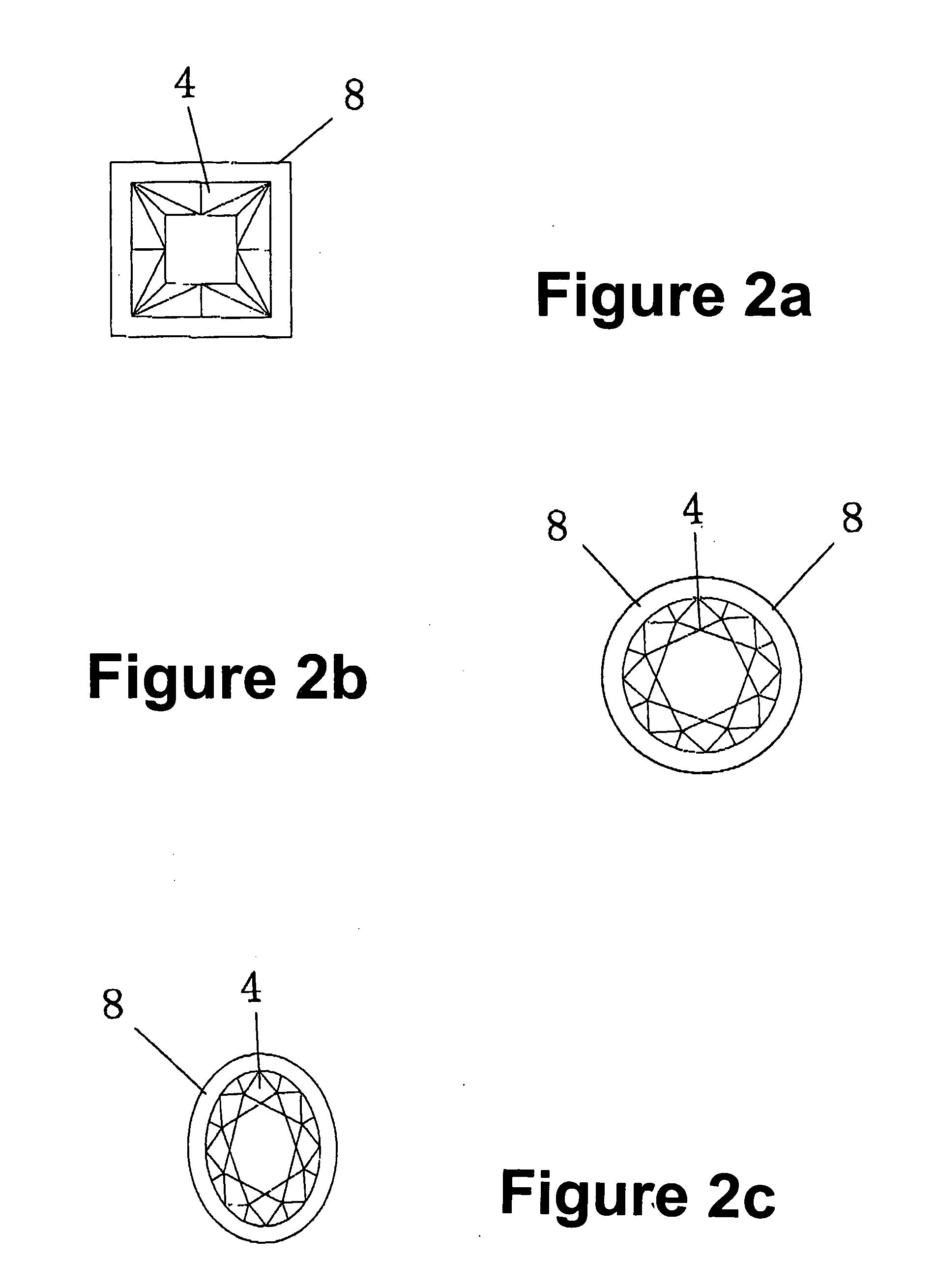
[0028]The bottom layer design forms a tube position for even support of the stone. The shape of the tube conforms to the shape of the stone. Commonly, the shape is circular, rectangular or square. After an electroforming process, the inner space of the tube presents a metal tubular seat which holds the stone thereon, preventing the stone from moving from front to back or left to right.

[0029]The surface layer design makes the stone receive downward pressure or transverse pressure. Thus, the stone, though without any pre-set me...


PUM

PropertyMeasurementUnit
conducting electricityaaaaaaaaaa
conductiveaaaaaaaaaa
sizeaaaaaaaaaa

Abstract

A method for setting at least one stone (4) in the surface of a jewelry and/or sculpture produced by electroforming comprising: a wax mandrel (1) which has a particularly designed tubular seat (5) and setting means (7, 8, 9). The wax mandrel (1) is then thoroughly painted with conductive coating (3) on its surface for conducting electricity. The stone (4) is then put in said tubular seat (5). During electroforming process, electroforming metal is deposited on said conductive coating (3) layer by layer and fills the gap between the stone (4) and the inlay position thus holds and sets the stone (4) in position. After electroforming, any redundant metal flake is removed by a scraper. Finally, said wax mandrel (1) and said conductive coating (3) are removed thermally and chemically. The method does not need to pre-set the stone (4) on a metal piece before electroforming, therefore the processing is simplified and thus greatly reduces the cost.

Description

FIELD OF THE INVENTION[0001]The present invention relates to the method for the setting of precious, semiprecious or synthetic stones into the surface of an electroformed piece and, more particularly, to the structural design of the specified inlay position in the wax mandrel for these stones setting.BACKGROUND OF THE INVENTION[0002]Nowadays, there are three ways to set stones into electroformed pieces. They are:[0003]1. To pre-set the stone on a metal piece, then insert the metal piece into the electroformed piece and fix the metal piece on the electroformed piece by laser welding, by flame welding or by mechanical clamping.[0004]2. To use glue to fix the stone directly on the surface of the electroformed piece.[0005]3. To insert a metal piece pre-set with stone into a wax mandrel which is to be electroformed. The wax mandrel has been pre-painted with a layer of conductive coating. The surface of the wax mandrel thus becomes electrically conductive. Consequently, the wax mandrel ca...

Claims


Application Information

Patent Timeline
Patent Type & Authority Applications(United States)
IPC IPC(8): A44C27/00B23P25/00
CPCA44C17/04Y10T29/49588Y10T29/49885
Inventor PANG, SIU CHUNG
Owner K & M JEWELRY
Why Eureka
Try Eureka