Method for bending metal material, bending machine, bending-equipment line, and bent product

a metal material and bending machine technology, applied in the direction of machines/engines, manufacturing tools, transportation and packaging, etc., can solve the problems of difficult to prevent non-uniform distortion, low degree of quenching accuracy, and inability to accurately control the cooling speed, so as to achieve the effect of reducing the generation of seizure defects and ensuring the accuracy of the bending operation

Inactive Publication Date: 2008-03-20
SUMITOMO METAL IND LTD +1
View PDF6 Cites 45 Cited by
  • Summary
  • Abstract
  • Description
  • Claims
  • Application Information

AI Technical Summary

Benefits of technology

[0042] According to the method for bending a metal material, the bending machine, and the bending equipment line in accordance with the above-described aspects of the present invention, even when a metal material is bent in various shapes, such as in a two-dimensional continuous bending operation in which the metal material is two-dimensionally bent in different directions (for example, an S shape) or in a three-dimensional continuous bending operation in which the metal material is three-dimensionally bent in different directions, and even when a metal material having high strength is bent, the metal material is uniformly cooled down, whe...

Problems solved by technology

However, in the grab bending method disclosed in Japanese Patent Application Publication No. 50-59263 and Japanese Patent No. 2816000, since the feeding speed of the metal tube varies significantly, the cooling speed cannot be accurately controlled, and a high degree of quenching accuracy cannot be ensured, which makes it difficult to prevent the occurrence of non-uniform distortion.
Thus, products made by the grab bending method are not suitable for parts of an automobile.
Furthe...

Method used


Image

  • Method for bending metal material, bending machine, bending-equipment line, and bent product
  • Method for bending metal material, bending machine, bending-equipment line, and bent product
  • Method for bending metal material, bending machine, bending-equipment line, and bent product

Examples


Embodiment Construction

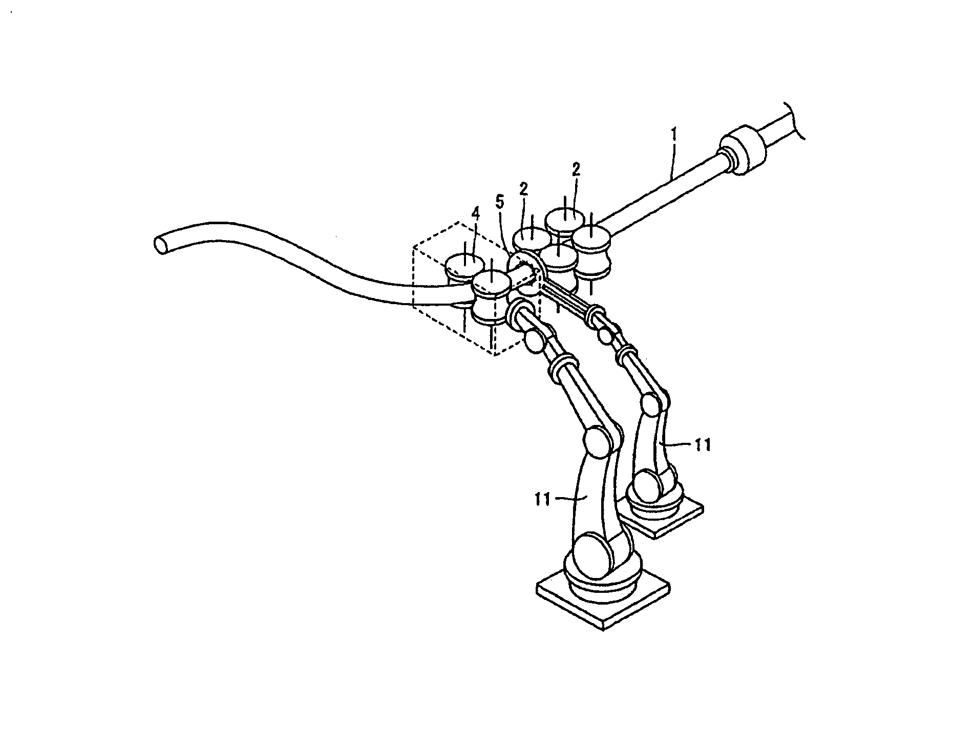
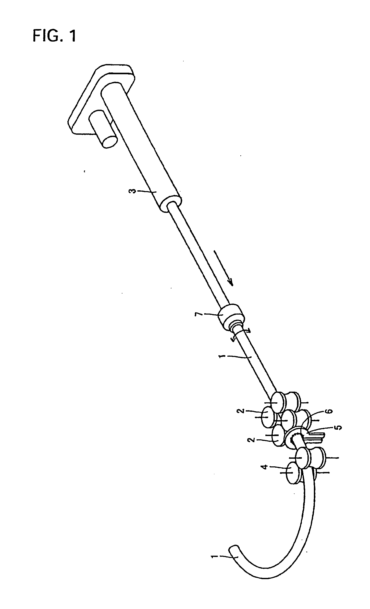
[0058] Hereinafter, the overall structure of a bending machine, the structure of a supporting unit, the structure of a machining unit, the structures of heating and cooling units, the structure of a movable roller die, the operation of a preheating unit, the structure and layout of an articulated robot, and the characteristics of a bending equipment line according to exemplary embodiments of the present invention will be described with reference to the accompanying drawings.

[0059] 1. Overall Structure of Bending Machine and Structure of Supporting Unit

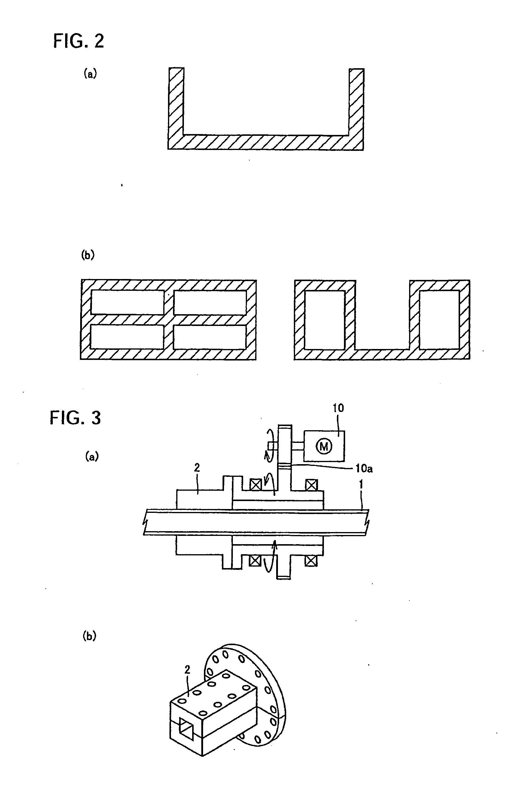
[0060]FIG. 1 is a diagram illustrating the overall structure of a bending machine for performing a bending operation according to the present invention. In the bending method, a metal material 1 as a workpiece that is rotatably supported by a supporting unit 2, is successively or continuously fed from an upstream side, and is then bent at a downstream side of the supporting unit 2.

[0061] The metal material 1 shown in FIG. 1 has a ci...


PUM

PropertyMeasurementUnit
Tensile strengthaaaaaaaaaa
Temperatureaaaaaaaaaa
Shapeaaaaaaaaaa

Abstract

A method, bending machine, and bending equipment line for bending a workpiece involves successively or continuously feeding the workpiece held by a supporting unit from an upstream side of the supporting unit, and performing bending at a downstream side of the supporting unit. The bending method includes: supporting the metal material with a movable roller die; controlling the position of the movable roller die and/or the moving speed of the metal material; heating the metal material in a temperature range in which the heated portion can be plastically deformed and in a temperature range in which quenching can be performed, by using a heating unit that is provided around the outer circumference of the metal material, to apply a bending moment to the heated portion; and rapidly cooling the heated portion, by using a cooling unit that is provided around the outer circumference of the metal material.

Description

TECHNICAL FIELD [0001] The present invention relates to a method for bending a metal material, a bending machine, and a bending-equipment line, and more particularly, to a method for effectively bending a metal material through a two-dimensional continuous bending operation in which the metal material is two-dimensionally bent in different directions (for example ending in a S shape) or a three-dimensional continuous bending operation in which the metal material is three-dimensionally bent in different directions, to a bending machine and a bending-equipment line to which the bending method can be applied, and to a bent product made by the bending machine or the bending-equipment line. BACKGROUND ART [0002] In recent years, demands for structural metal materials having high strength and light weight have increased in consideration of global environment. For example, in an automobile industry, there are growing demands for a safe car body and high-strength and light-weight parts of a...

Claims


Application Information

Patent Timeline
IPC IPC(8): B21D31/00
CPCY10T428/12292B21D7/08
Inventor TOMIZAWA, ATSUSHIKIKUCHI, FUMIHIKOKUWAYAMA, SHINJIRO
Owner SUMITOMO METAL IND LTD
Why Eureka
Try Eureka