Means and apparatus for a scalable congestion free switching system with intelligent control

a technology of intelligent control and switching system, applied in electrical equipment, data switching networks, digital transmission, etc., can solve problems such as problems that cannot be addressed, problems that cannot be solved, and inability to scale up internet switches, so as to reduce the amount of circuitry needed, and simplify processing

Inactive Publication Date: 2008-03-20
INTERACTIC HLDG LLC
View PDF7 Cites 153 Cited by
  • Summary
  • Abstract
  • Description
  • Claims
  • Application Information

AI Technical Summary

Benefits of technology

[0075]FIG. 1E is a schematic block diagram showing an example of a full system of the type shown in FIG. 1A where the request switch and data switch system are combined in a single component, which advantageously can simplify processing in certain applications, and reduce the amount of circuitry needed to implement the

Problems solved by technology

There are two significant requirements associated with implementing a large Internet switch that are not feasible to implement using prior art.
But there are still problems that must be addressed.
In real-life conditions, global traffic management is less than optimal, so that for a prolonged time traffic can en

Method used


Image

  • Means and apparatus for a scalable congestion free switching system with intelligent control
  • Means and apparatus for a scalable congestion free switching system with intelligent control
  • Means and apparatus for a scalable congestion free switching system with intelligent control

Examples


second embodiment

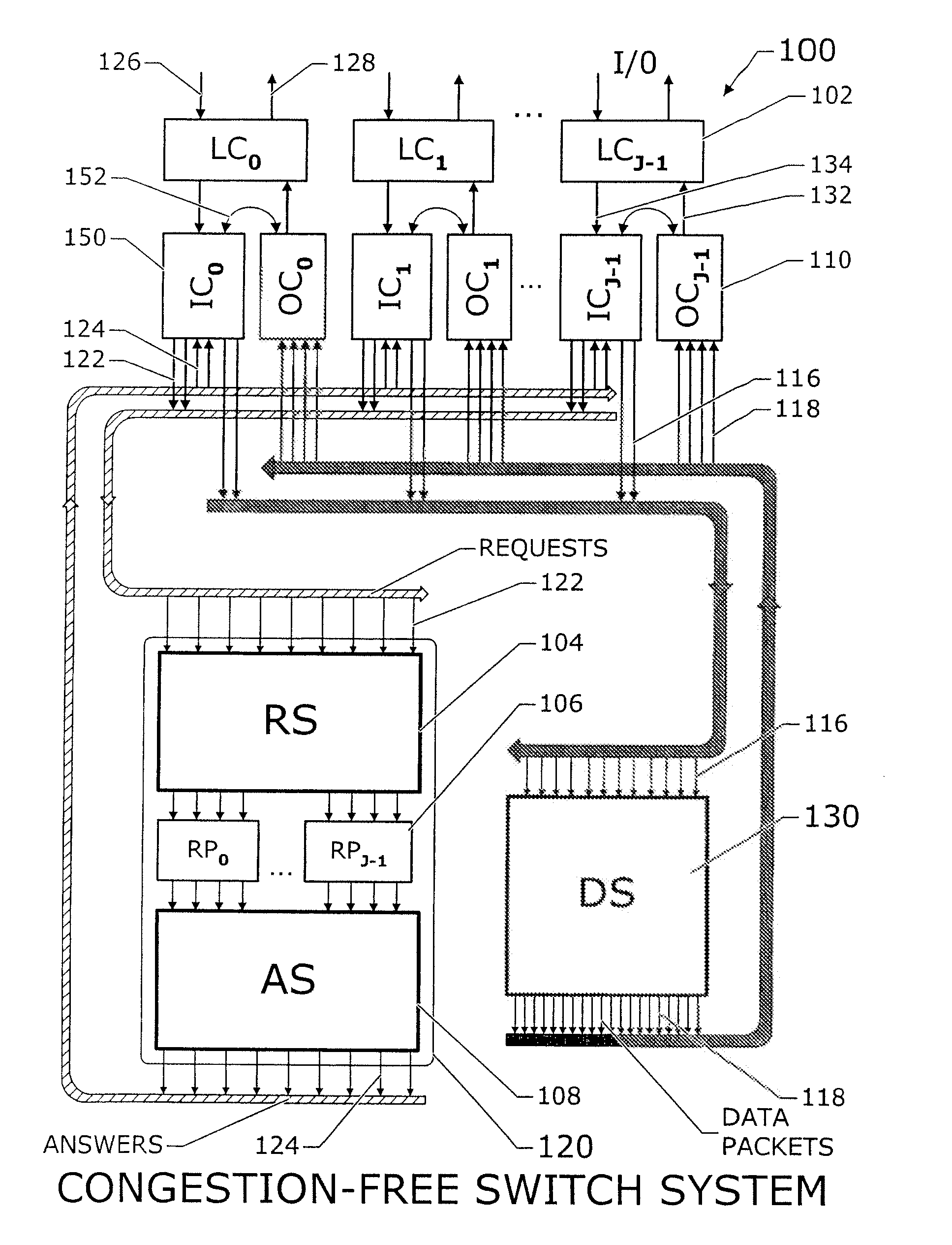
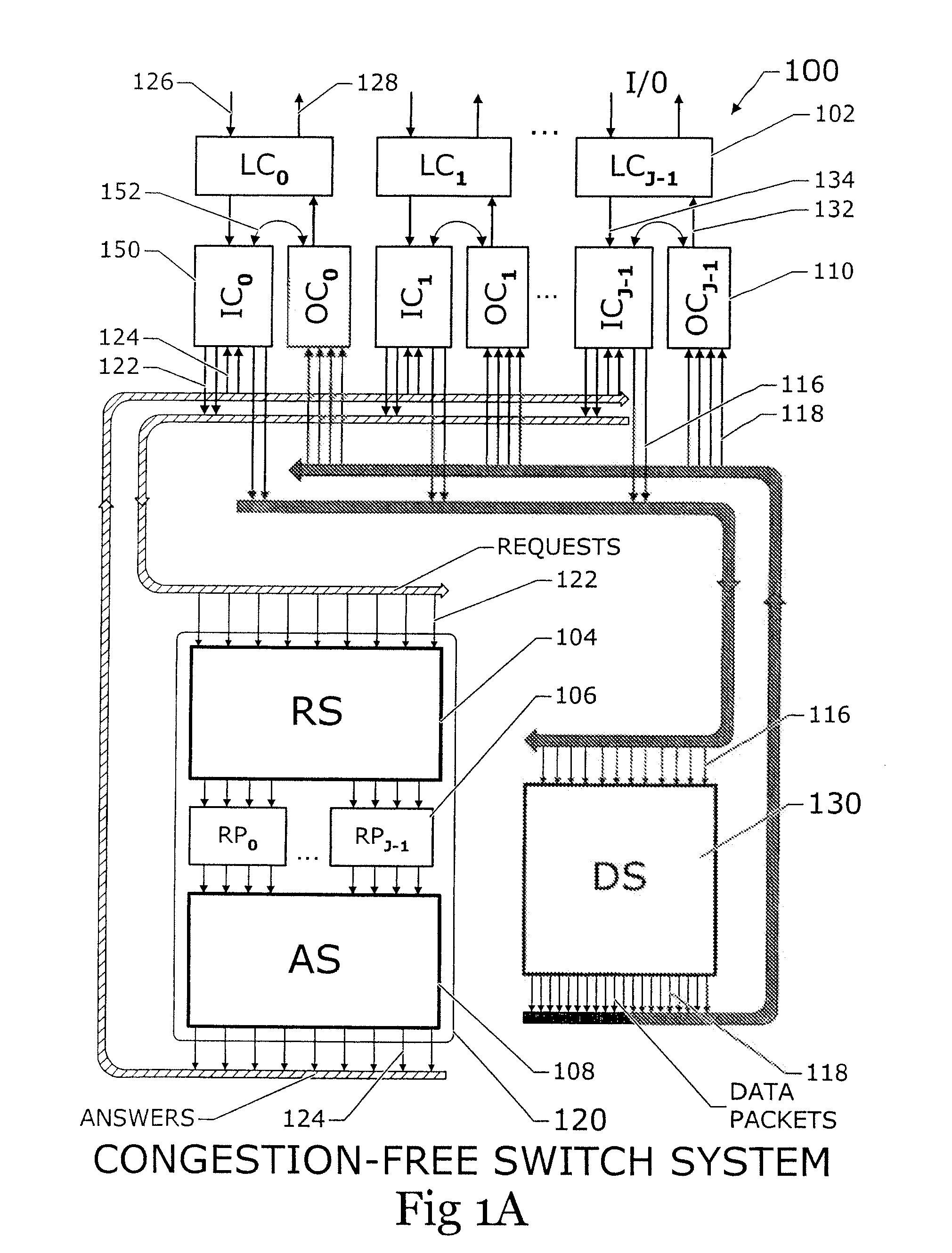
[0154] It should be noted that in the case of an embodiment utilizing multiple paths connecting the input and output controllers to the rest of the system, all three switches, RS 104, AS 108, and DS 130, can deliver multiple packets to the same address. Switches with the capability to handle this condition must be used in all three locations. In addition to the obvious advantage of increased bandwidth, this embodiment allows the request processors to make more intelligent decisions since they base their decisions on a larger data set. In a second embodiment, request processors advantageously can send a plurality of urgent packets from one input controller ICn with relatively full buffers to a single output controller OCm, while refusing requests from other input controllers with less urgent traffic.

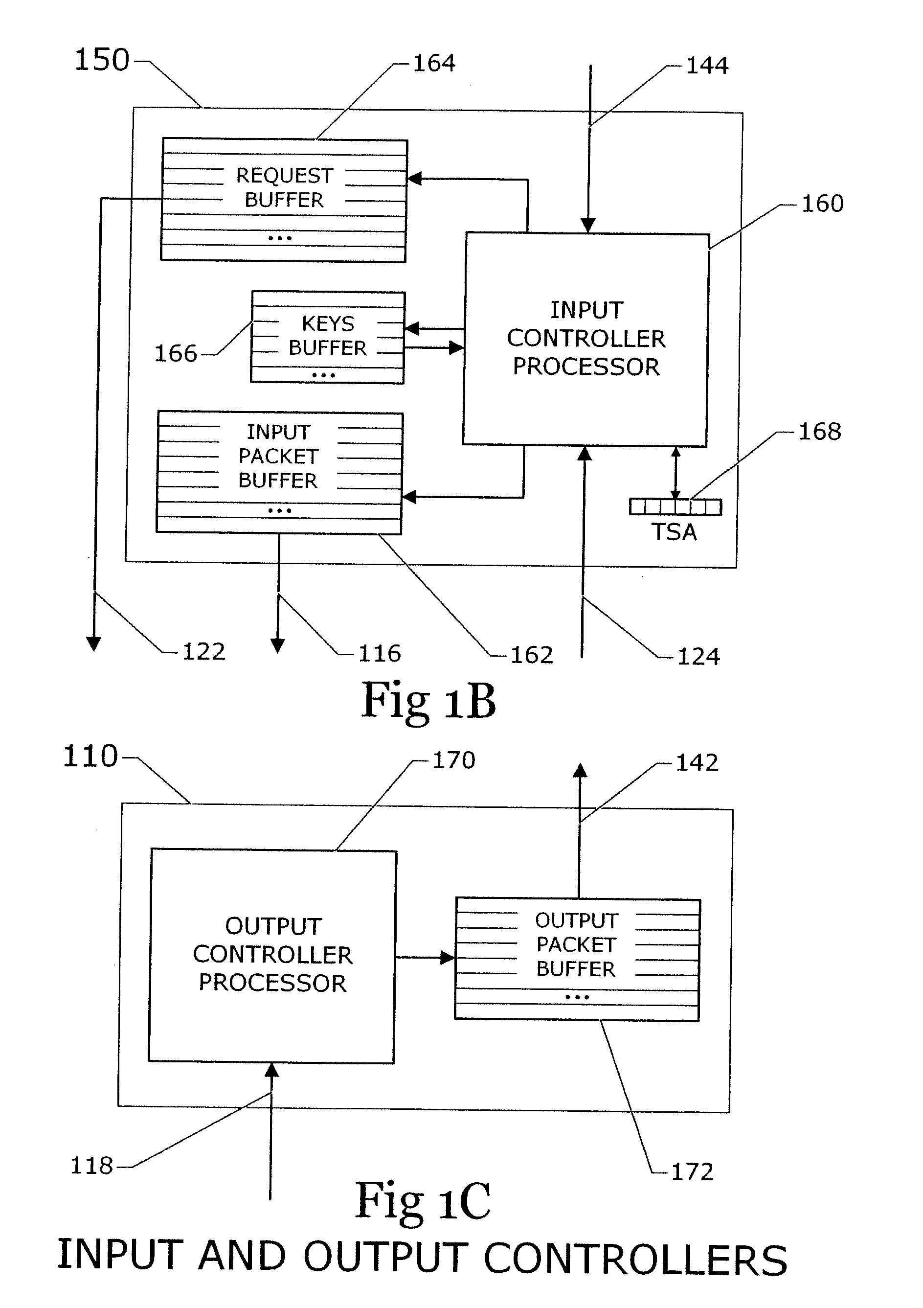
[0155] Referring also to FIGS. 1B, 1C and 6A, in the operation of system 100 events occur at given time intervals. At time T0, there are a number of input controller processors 160 that h...

first embodiment

[0188] In a first embodiment, the request packet is of the form illustrated in FIG. 2D. These request packets are injected into RS / DS switch 156. In one scheme, these request packets are injected into the RS / DS switch at the same time as the data packets. In another scheme, these packets are injected at special request-packet-injection times. Since the request packets are generally shorter than data packets, the multiple-length-packet switch embodiment of a previous section can be advantageously used for this purpose.

[0189] In a second embodiment, the request packet is also a segment packet as illustrated in FIG. 2F. The input controller sends the first segment, S0, of a packet through the RS / DS switch. When S0 arrives at the request processor section of RP / OCN, the request processor decides whether to allow the sending of the rest of the segments of the packet, and if the rest of the segments are allowed, the request processor schedules the sending of those segments. These decision...

embodiment

[0272] Twisted Cube Embodiment

[0273] The basic system consisting of a data switch and a switch management system is depicted in FIG. 1A. Variants to increase the bandwidth of the system without increasing the number of input and output ports are illustrated in FIGS. 9, 10A and 10B. The purpose of the present section is to show how to increase the number of input ports and output ports while simultaneously increasing the total bandwidth. The technique is based on the concept of two “twisted cubes” in tandem, where each cube is a stack of MLML switch fabrics. A system that contains MLML networks and concentrators as components is described Invention #4. An illustration of a small version of a twisted cube system is illustrated in FIG. 11A. System 1100 can be either electronic or optical; it is convenient to describe the electronic system here. The basic building block of such a system is an MLML switch fabric of the type taught Inventions #2 and #3 that has N rows and L columns on eac...


PUM


Abstract

This invention is directed to a parallel, control-information generation, distribution and processing system. This scalable, pipelined control and switching system efficiently and fairly manages a plurality of incoming data streams, and applies class and quality of service requirements. The present invention also uses scalable MLML switch fabrics to control a data packet switch, including a request-processing switch used to control the data-packet switch. Also included is a request processor for each output port, which manages and approves all data flow to that output port, and an answer switch which transmits answer packets from request processors back to requesting input ports.

Description

CROSS-REFERENCE TO RELATED APPLICATIONS [0001] The disclosed system and operating method are related to subject matter disclosed in the following patents and patent applications that are incorporated by reference herein in their entirety: [0002] U.S. Pat. No. 6,289,021 (application Ser. No. 09 / 009,703), issued Sep. 11, 2001, entitled “A Scaleable Low-Latency Switch for Usage in an Interconnect Structure,” naming John Hesse as inventor; [0003] U.S. Pat. No. 5,996,020 (application Ser. No. 08 / 505,513), issued Nov. 30, 1999, entitled “A Multiple Level Minimum Logic Network,” naming Coke Reed as inventor; [0004] U.S. Pat. No. 6,754,207 (application Ser. No. 09 / 693,359), issued Jun. 22, 2004, entitled, “Multiple Path Wormhole Interconnect,” naming John Hesse as inventor; [0005] U.S. Pat. No. 6,687,253 (application Ser. No. 09 / 693,357), issued Feb. 3, 2004 entitled, “Scalable Wormhole-Routing Concentrator,” naming John Hesse and Coke Reed as inventors; [0006] U.S. patent application Ser. ...

Claims


Application Information

Patent Timeline
IPC IPC(8): H04L12/28H04L12/56
CPCH04L49/254H04L47/12H04L45/42H04L49/253
Inventor REED, COKEHESSE, JOHN
Owner INTERACTIC HLDG LLC
Why Eureka
Try Eureka