
Transmission parameter recognition apparatus and method thereof

a technology of parameter recognition and recognition apparatus, which is applied in multiplex communication, amplitude demodulation, mechanical sense of coincidences, etc., can solve the problems of not effectively reducing the complexity of hardware architecture and lowering the power consumption in practice, and achieves the effect of simplifying the complexity of hardware architecture and lowering power consumption

Inactive Publication Date: 2008-03-20
SUNPLUS TECH CO LTD
View PDF10 Cites 2 Cited by
  • Summary
  • Abstract
  • Description
  • Claims
  • Application Information

AI Technical Summary

Benefits of technology

[0015]Accordingly, the present invention is directed to provide a transmission parameter recognition apparatus capable of reducing the complexity and power consumption thereof by using a correlation symbol summing module to generate an energy interval impliedly containing the transmission mode information and the guard interval information.
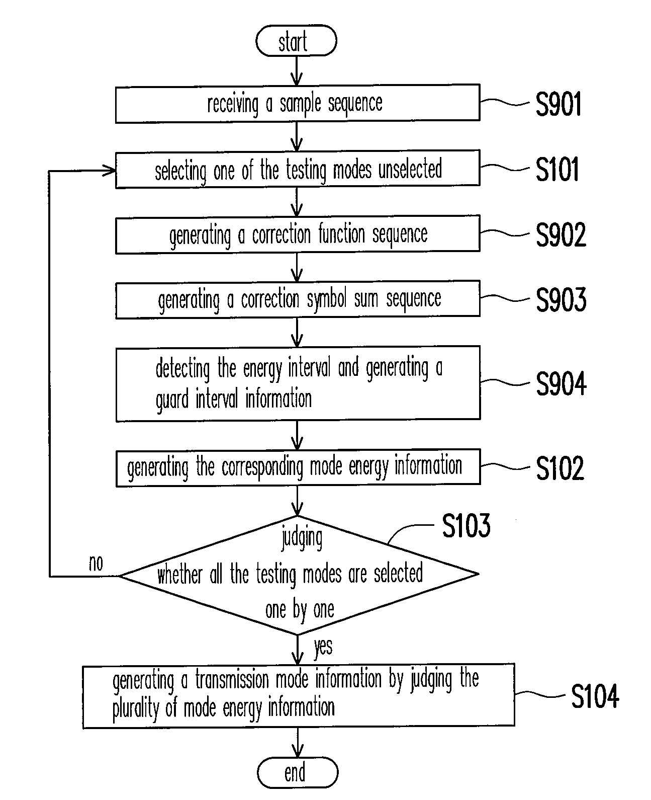
[0016]The present invention is also directed to provide a transmission parameter recognition method capable of effectively reducing the complexity and power consumption of the hardware architecture by detecting an energy interval of the correlation symbol sum sequence.
[0027]By using a correlation symbol summing module to generate an energy interval, the present invention enables the energy interval detection module thereof to reveal the energy interval distribution, followed by obtaining the guard interval type of the sample sequence, so as to achieve the goal of simplifying the hardware architecture complexity and lowering the power consumption.

Problems solved by technology

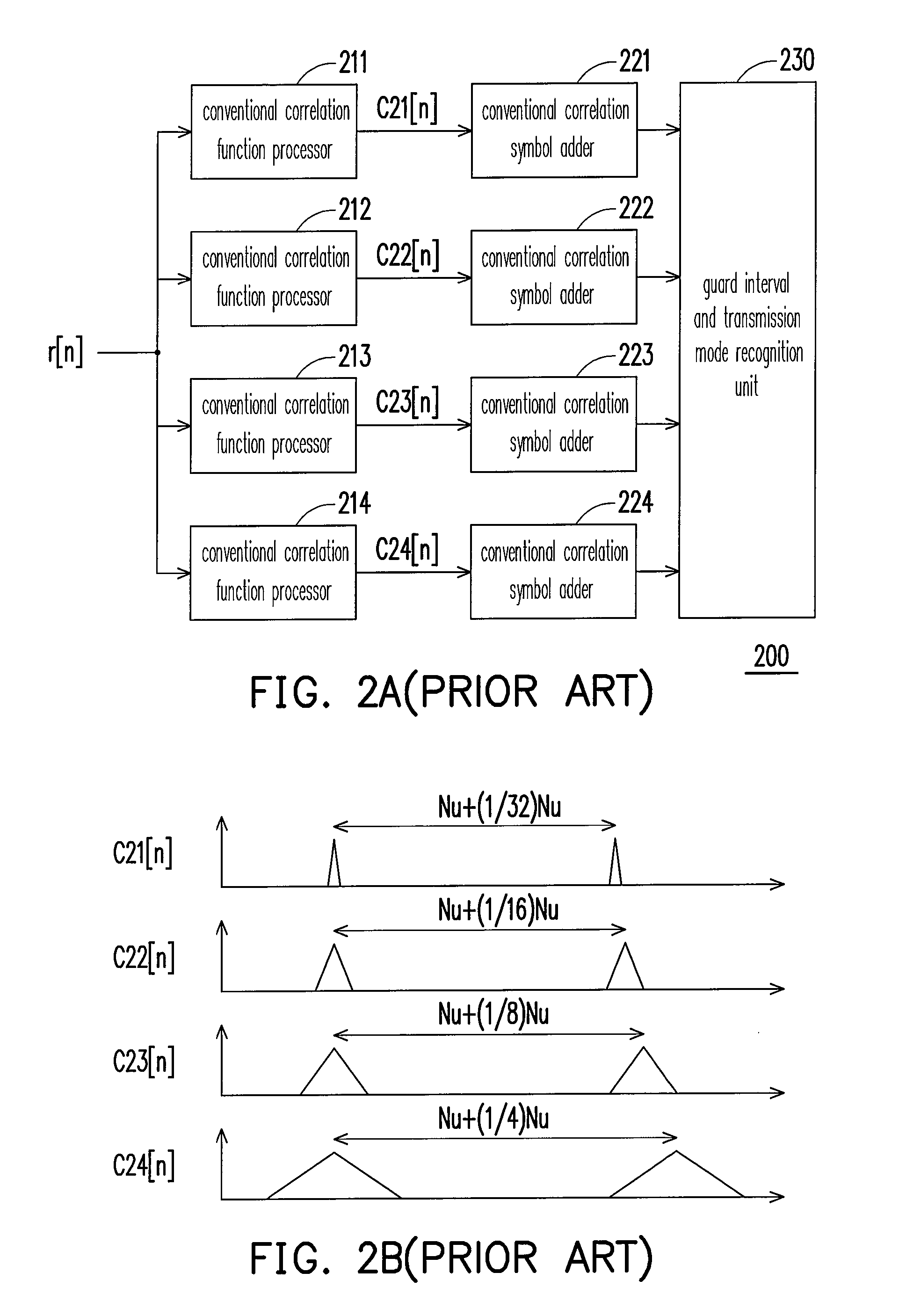
In other words, the conventional transmission parameter recognition apparatus 300, limited by using a plurality of conventional correlation symbol adders, can not effectively reduce the hardware architecture complexity and lower the power consumption in practice.

Method used


Image

  • Transmission parameter recognition apparatus and method thereof
  • Transmission parameter recognition apparatus and method thereof
  • Transmission parameter recognition apparatus and method thereof

Examples


Embodiment Construction

[0041]The primary technical feature of the present invention resides in utilizing an energy interval generated by the correlation symbol summing module to judge various guard interval types. Compared to the prior art, the transmission parameter recognition apparatus of the present invention is capable of reducing the complexity of the hardware architecture thereof and the power consumption. Furthermore, the present invention also realizes miniaturization and portability for the receiver employing the transmission parameter recognition apparatus.

[0042]FIG. 4 is an architecture diagram of a transmission parameter recognition apparatus according to a preferred embodiment of the present invention. Referring to FIG. 4, a transmission parameter recognition apparatus 400 includes a correlation function processing module 410, a correlation symbol summing module 420 and an energy interval detection module 430, wherein the correlation symbol summing module 420 is coupled to the correlation fu...


PUM


Abstract

A transmission parameter recognition apparatus and the method thereof are disclosed. The transmission parameter recognition apparatus includes a correlation function processing module, a correlation symbol summing module and an energy interval detection module. The correlation function processing module computes a correction between two adjoining symbols in a sample sequence to generate a correlation function sequence. The correlation symbol summing module accumulates M symbols in the correlation function sequence to generate an energy interval. Since the distribution of the energy interval is related to the guard interval type, therefore, the energy interval detection module detects the distribution of the energy interval to generate a piece of guard interval information.

Description

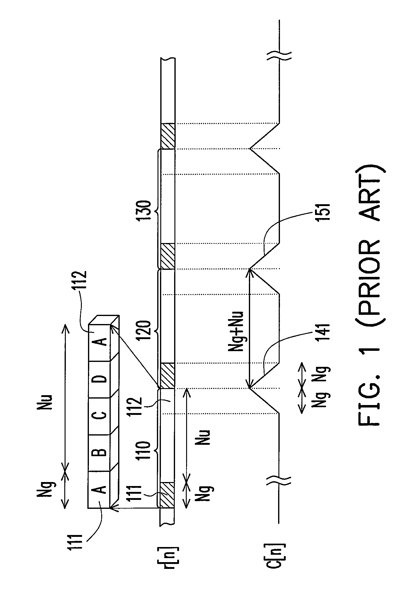
CROSS-REFERENCE TO RELATED APPLICATION[0001]This application claims the priority benefit of Taiwan application serial no. 95133982, filed Sep. 14, 2006. All disclosure of the Taiwan application is incorporated herein by reference.BACKGROUND OF THE INVENTION[0002]1. Field of the Invention[0003]The present invention generally relates to a transmission parameter recognition apparatus, and more particular, to a transmission parameter recognition apparatus for recognizing the guard interval type and the transmission mode.[0004]2. Description of Related Art[0005]In the digital communication field, every symbol transmitted by an orthogonal frequency division multiplexing system (OFDM system) includes a data interval and a guard interval. A transmission terminal can transmit data intervals in different lengths according to different transmission modes, and each transmission mode can select a guard interval with an appropriate length to avoid an inter-symbol interference (ISI) caused by the ...

Claims


Application Information

Patent Timeline
IPC IPC(8): G06K21/02
CPCH04L27/2607H04L27/2666H04L27/2647H04L27/2662
Inventor YANG, FANG-MINGHUNG, CHING-PIAO
Owner SUNPLUS TECH CO LTD
Learn More