

Wind turbine and operating method thereof
a technology of wind turbine and operating method, which is applied in the direction of mechanical power/torque control, program control, wind energy generation, etc., can solve the problems of increasing the rotational speed of the wind turbine and the inability to control the rotational speed of the rotor, so as to prevent overspeed in the wind turbine and improve the accuracy of pitch angle control
- Summary
- Abstract
- Description
- Claims
- Application Information
AI Technical Summary
Benefits of technology
Problems solved by technology
Method used
Image

Examples
first embodiment
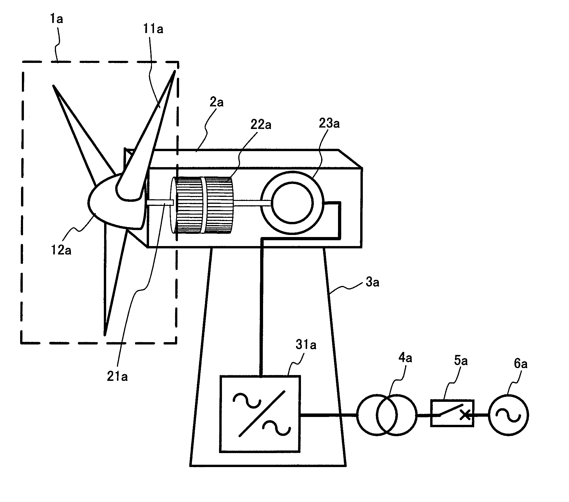
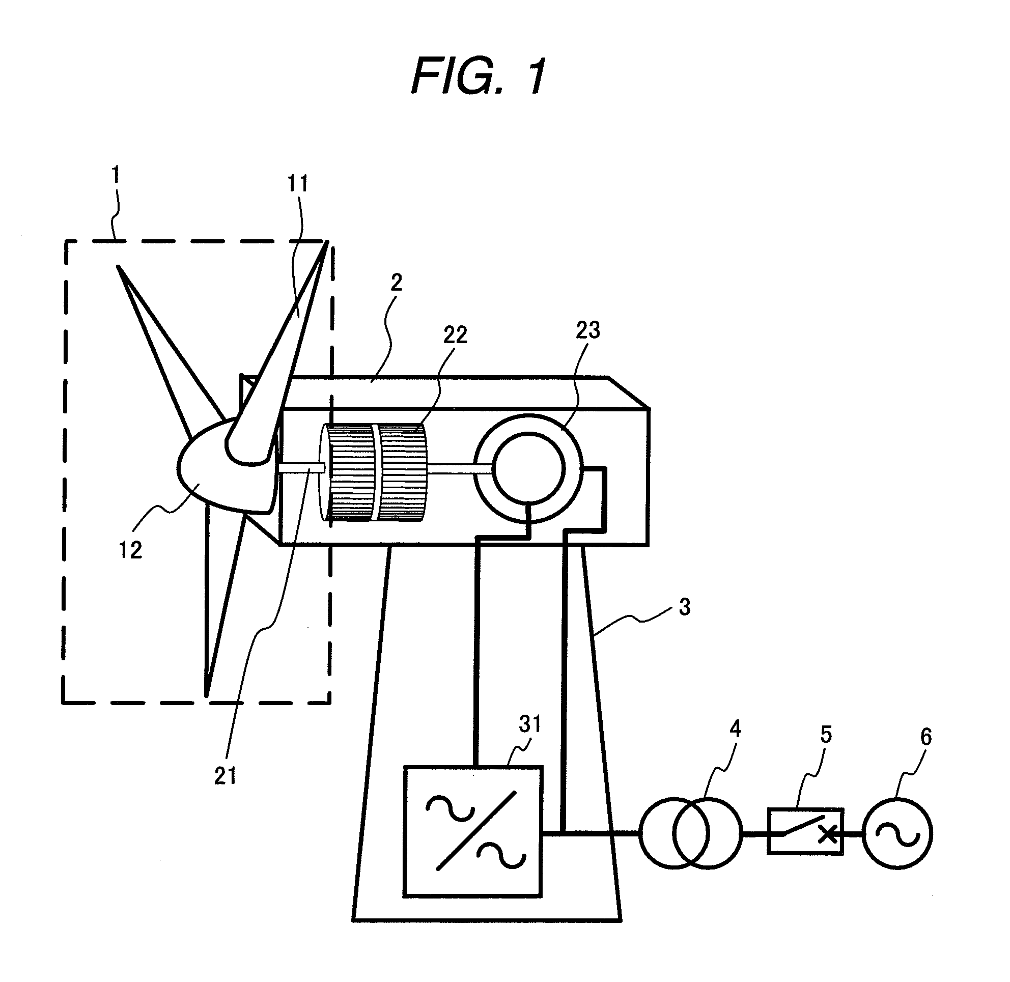
[0031]The structure of a wind turbine in a first embodiment of the present invention will be described first with reference to FIG. 1. The wind turbine receives wind by use of blades 11 and converts the wind energy into rotational energy. The rotational energy rotates a hub 12 to which the blades 11 are attached. The rotational part comprising the blades 11 and hub 12 is referred to as a rotor 1. The rotation of the rotor 1 is transmitted to an accelerating gear 22 through a shaft 21. The accelerating gear 22 changes the rotational speed of the rotor 1 to another rotational speed suitable for a power generator 23. In FIG. 1, a doubly-fed generator is shown as the power generator 23. In the doubly-fed generator, a power grid and a power converter are connected to the stator winding and the rotor winding, respectively, through a slip ring. The present invention can be used even when the power generator 23 is a permanent magnet generator or induction generator 23a.
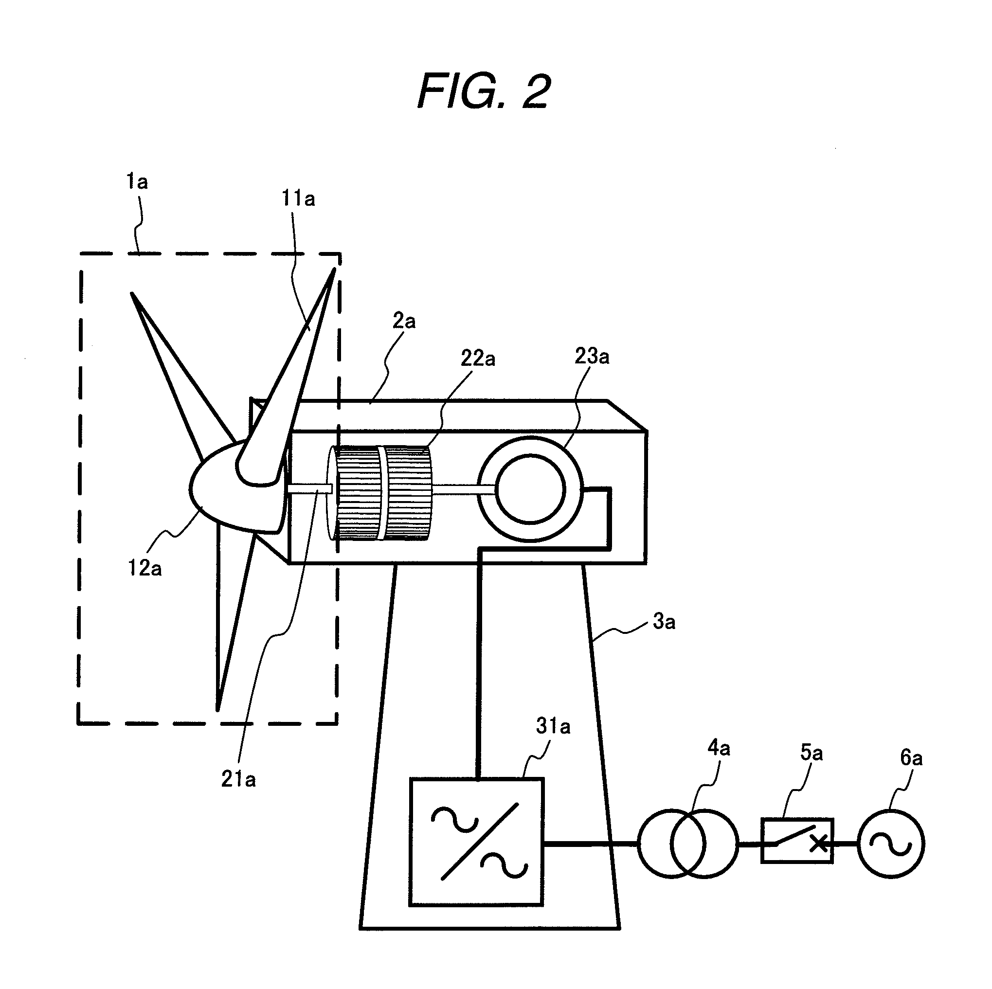
[0032]FIG. 2 shows a...
second embodiment
[0044]A second embodiment of the present invention differs from the first embodiment in that the wind turbine has a rotational speed detector in the rotor.
[0045]In case of a system voltage drop due to a grid fault, wind turbines have been allowed to be disconnected from the power grid. As more wind turbines have been linked recently, this regulation is being changed. When, for example, several tens to several hundreds of wind turbines, each having a capacity of 500 kW to several megawatts, are disposed in a single place, a total power generation capacity reaches hundreds of megawatts. This type of large-scale wind power facility needs to be handled in the same way as large power generating facilities such as conventional thermal power plants and hydroelectric power plants. When the above large-scale wind power facility is disconnected from the power grid at the time of a temporary voltage drop in the power grid, the power grid is affected as if a large power generating facility were...
third embodiment
[0076]FIG. 20 is a structural diagram of a wind turbine according to a third embodiment of the present invention. In this embodiment, a rotational speed detector is connected to one end of the shaft in the nacelle, and a detected rotational speed value signal is transmitted to the rotor 1 through a wire in the shaft.
[0077]In this embodiment, as shown in FIG. 20, the rotary encoder 126 is disposed at one end of the shaft 21 in the nacelle 2. In the present invention, the rotary encoder 126 is disposed differently from the conventional rotary encoder so that the detected rotational speed value is transmitted to the inside of the rotor 1 without passing through the slip ring. In the conventional structure, the rotating part of the rotary encoder is fixed to the shaft 21, and the fixed part is fixed to the nacelle 2. Conversely, in this embodiment, the rotational part of the rotary encoder 126 is fixed to the nacelle 2, and the fixed part is fixed to the shaft 21. The signal line connec...
PUM
 Abstract
Description
Claims
Application Information