
Polishing end point detection method utilizing torque change and device thereof

a detection method and torque change technology, applied in the direction of force/torque/work measurement apparatus, lapping machines, instruments, etc., can solve the problems of sudden reduction or the like at the polishing end point in the torque change, the polishing end point cannot be detected, so as to achieve reliable detection, reduce the torque of the polishing, and high precision

Inactive Publication Date: 2008-03-20
TOKYO SEIMITSU
View PDF4 Cites 23 Cited by
  • Summary
  • Abstract
  • Description
  • Claims
  • Application Information

AI Technical Summary

Benefits of technology

[0024] According to this configuration, the detected torque is subjected to moving average processing to provide torque input; therefore, the oscillation components in the detected torque comprising actual measurement values from a rotation drive source such as a motor are removed. After average value acquisition for the n times of sampling of the torque input, the torque input is assumed to be relative input which is a relative value with respect to the average value; therefore, even when differences are generated in the torque input due to individual differences in the conductive film to be polished on the wafer, influence to polishing end detection is eliminated. Then, the changed amount of the relative input in each predetermined time interval is assumed to be a torque input area of the predetermined time interval reduced to an area. When the added torque input area which is obtained by adding the torque input areas is compared with a threshold value which is provided in advance, the polishing end of the conductive film to be polished is detected while preventing erroneous detection of the polishing end, for example, in the case in which the torque input is rapidly changed or the case in which it is gently varied by a large or small amount.
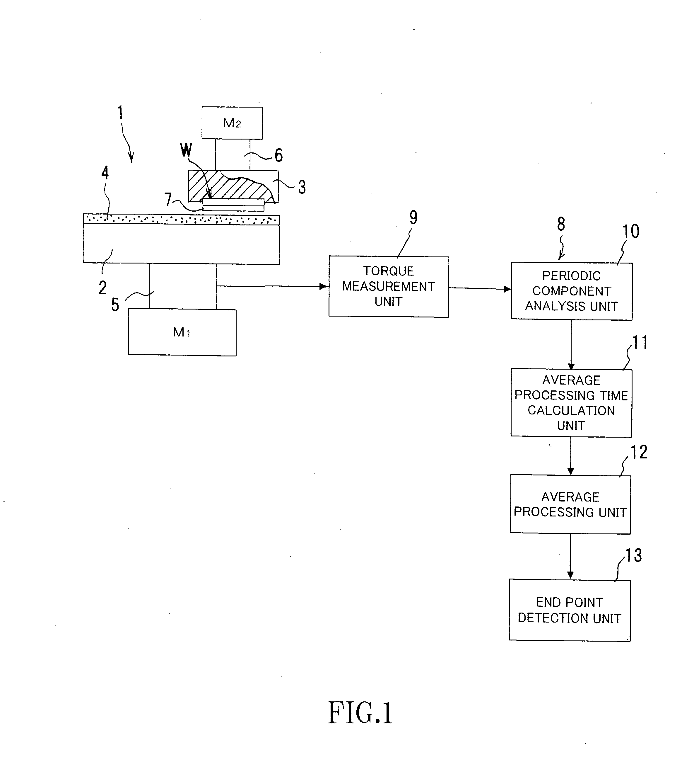
[0052] In the tenth aspect of the present invention, the measured data is subjected to Fourier transformation so as to analyze a plurality of periodic components in the data by the periodic component analysis means, a plurality of moving average processing time corresponding to the plurality of periodic components is calculated by the average processing time calculation means, and a plurality of averaging processes are performed based on the plurality of moving average processing time calculated in real time for the data so as to correct the waveform by the average processing means. Therefore, in the case in which the data representing the torque of the polishing measured by the torque measurement means includes the plurality of periodic components such as the fixed periodic components and the periodic components which are continuously varied in real time, when the moving average processing time is calculated in real time respectively for the plurality of periodic components, and the data is subjected to a plurality of averaging processes by the average processing means by the moving average processing time calculated in real time, there is an advantage that the torque waveform from which the plurality of periodic noise components are removed can be efficiently obtained from the data.

Problems solved by technology

However, the torque waveform itself includes various disturbances.
Therefore, the polishing end point cannot be detected merely by simply monitoring the change in the torque waveform.
However, there is sudden reduction or the like at the polishing end point in the torque change upon polishing of the conductive film on the wafer.
Therefore, when the box is applied, there is a problem that the polishing end point cannot be detected unless the condition that UPs and DOWNs are continuously detected n times is satisfied, and the polishing end point is erroneously detected when the polishing torque of an conductive film on a wafer having an individual difference.
Therefore, analysis of the inclination degree (numerical value) of the waveform is not performed, parallel use of an application algorithm is difficult, and detecting the polishing end point in real time is difficult.
Moreover, disturbances of drift components such as the surface state of a polishing pad cannot be removed.
However, for example, low-frequency noise cannot be removed merely by the low pass filter.
However, in such series of parts, the noise state during polishing is expected to be constant at the beginning and after finish of the polishing, and the case in which it is changed merely in the vicinity of polishing end is expected.
The method for removing fixed noise has been described in the conventional technique; however, such method can never be utilized for removing the disturbance components of the torque waveform in device wafer planarization, since the periodic components that continuously varies in real time is more dominant as disturbance elements in planarization CMP rather than the fixed periodic components such as the platen or polishing head.
Also, it is obvious that it cannot be removed even by the low pass filter.
Therefore, even when the periodic waveform variation is removed, removing the noise that gradually varies along with the change in the surface state of the polishing pad is difficult, and it is expected that such disturbances are erroneously detected in the conventional method.
Therefore, when the box is applied, there is a problem that the polishing end point cannot be detected unless the condition that UPs or DOWNs are continuously detected n times is satisfied, and there is a possibility that the polishing end point is erroneously detected when the polishing torque of the conductive film on the wafer having an individual difference is monitored.
However, since there are individual differences in the conductive films on wafers, when the sampled torque value itself is compared with the set value, which is provided in advance, the polishing end point may be erroneously detected as well as the above described case.

Method used


Image

  • Polishing end point detection method utilizing torque change and device thereof
  • Polishing end point detection method utilizing torque change and device thereof
  • Polishing end point detection method utilizing torque change and device thereof

Examples


Embodiment Construction

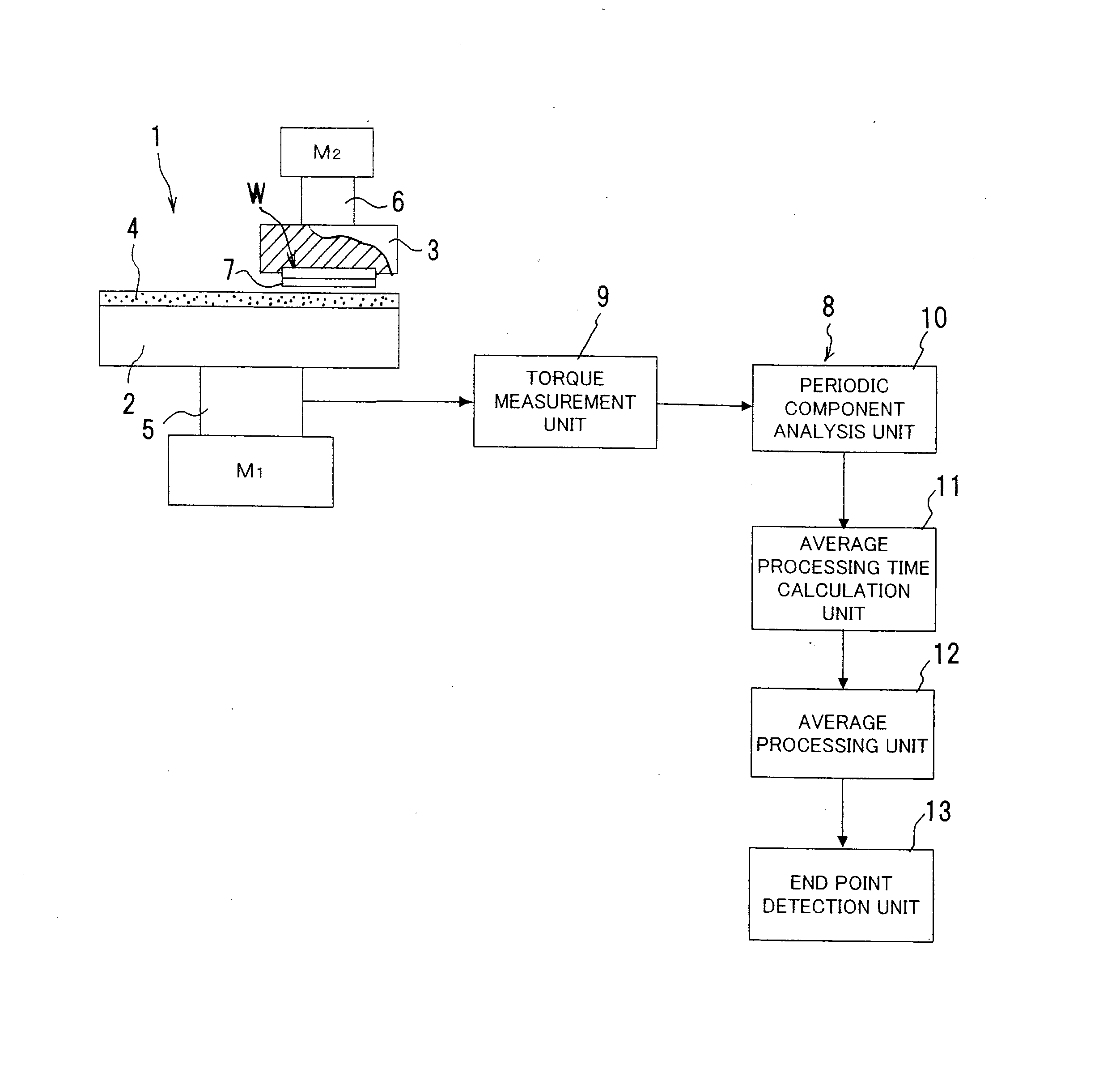
[0061] Hereinafter, a preferred embodiment of the present invention will be described in detail with reference to drawings. First of all, a configuration of a polishing end point detection device which is according to the present embodiment and utilizing torque change will be described. FIG. 1 is a block diagram of a schematic configuration of a chemical mechanical polishing device and the polishing end point detection device.

[0062] In FIG. 1, the chemical mechanical polishing device 1 is mainly composed of a platen 2 and a polishing head 3. The platen 2 is formed into a disk-like shape, a polishing pad 4 is attached to the upper surface thereof, and a platen motor M1 serving as a rotation drive source is coupled to the center of the lower surface thereof via a platen rotating shaft 5. The polishing head 3 is formed into a disk-like shape smaller than the platen 2 side and a head motor M2 serving as a rotation drive source is coupled to the center of the upper surface thereof via a...


PUM


Abstract

Change in a torque waveform is monitored while removing continuously-varied periodic noise in real time, and the change in the torque waveform caused purely by the wafer state is detected by separating noise components while removing the noise not caused by the wafer state such as drift noise cased by dressing conditions and the polishing pad state, thereby reliably detecting a polishing end point at high precision in the wafer state when polishing is finished. A polishing end point detection device utilizing torque change having a torque measurement means for measuring torque, a periodic component analysis means for analyzing periodic components in data by subjecting Fourier transformation to the measured data, an average processing time calculation means for calculating moving average processing time for removing periodic noise components based on the analyzed periodic components, an average processing means for correcting the waveform by performing averaging process based on the moving average processing time calculated in real time for the data, and an end point detection means for detecting the polishing end point of a predetermined film based on change in the corrected torque waveform is provided.

Description

FIELD OF THE INVENTION [0001] The present invention relates to a polishing end point detection method utilizing torque change and a device thereof and particularly relates to a polishing end point detection method utilizing torque change and device thereof capable of reliably detecting a polishing end point of an conductive film at high precision by monitoring change in a torque waveform while removing periodic noise, which continuously varies in chemical mechanical polishing processing (CMP: Chemical Mechanical Polishing), in real time. BACKGROUND OF THE INVENTION [0002] There is a known technique in which, when an conductive film on a wafer is to be subjected to chemical mechanical polishing, a polishing end point of the conductive film is detected by monitoring change in a torque waveform (for example, see U.S. Pat. No. 5,069,002). The torque waveform itself measured upon polishing of the conductive film on the wafer includes various disturbances. It is important how the torque w...

Claims


Application Information

Patent Timeline
IPC IPC(8): G06F19/00
CPCB24B37/013H01L22/26H01L21/3212B24B49/16
Inventor FUJITA, TAKASHIHASEGAWA, SATOSHIOSADA, SHINJIYAMADA, SOUSHIATARASHI, TAKUJI
Owner TOKYO SEIMITSU
Learn More