Control apparatus and control method for internal combustion engine
a control apparatus and internal combustion engine technology, applied in the direction of electric control, machines/engines, instruments, etc., can solve the problems of increasing the speed of internal combustion engine, and increasing the frequency of knocking, so as to improve fuel efficiency and increase the coolant temperature
- Summary
- Abstract
- Description
- Claims
- Application Information
AI Technical Summary
Benefits of technology
Problems solved by technology
Method used
Image
Examples
first embodiment
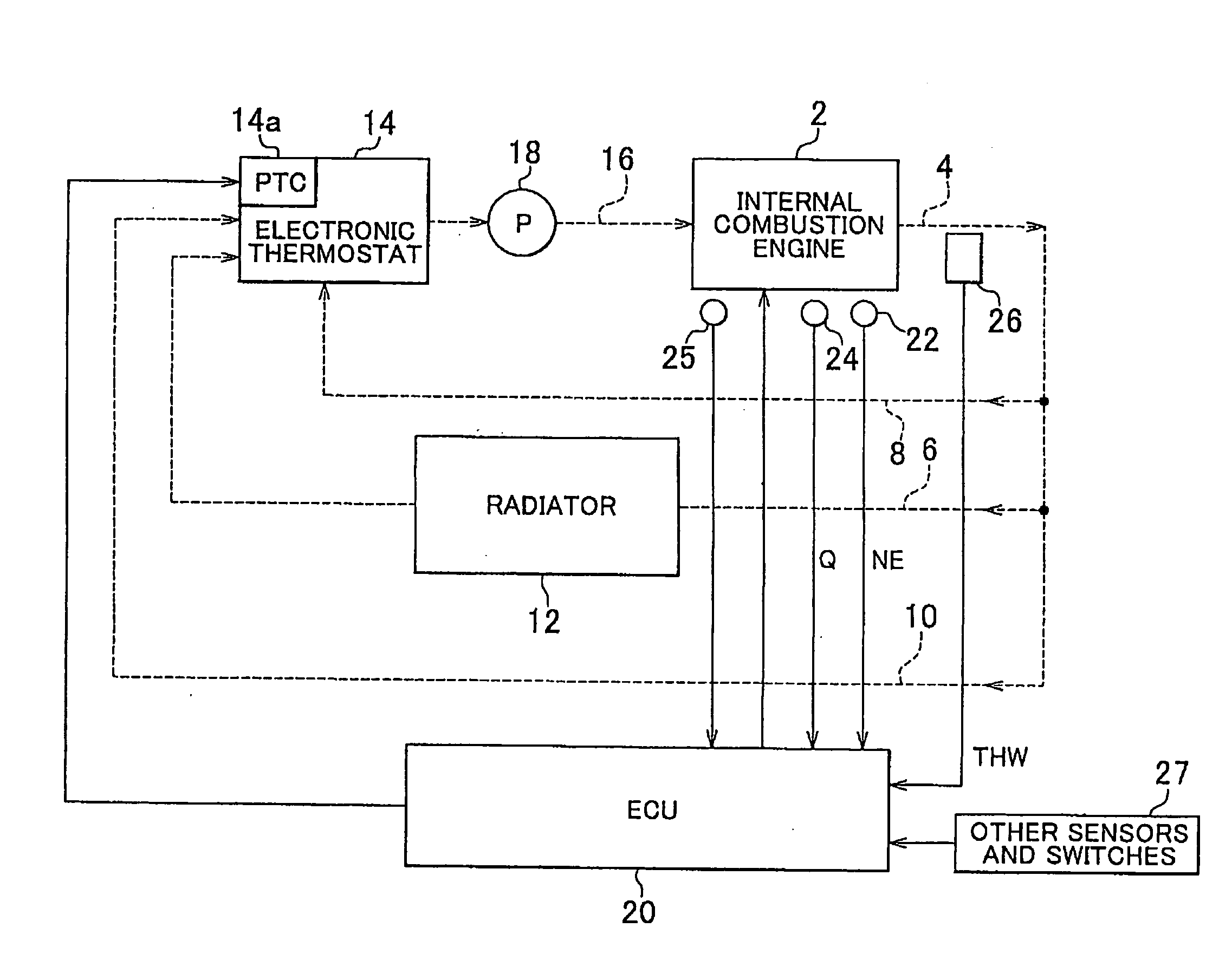
[0041]FIG. 1 is a block diagram showing the schematic configuration of a control apparatus for an internal combustion engine for a vehicle and a coolant temperature adjustment mechanism, to which the above-described invention is applied. The control apparatus for an internal combustion engine controls operation of an internal combustion engine 2. In addition, the control apparatus controls the temperature of the internal combustion engine 2 by adjusting the temperature of coolant that flows in a coolant passage that includes a water jacket formed in the cylinder block and the cylinder head of the internal combustion engine 2.
[0042]As shown in FIG. 1, after the coolant flows out of the internal combustion engine 2, the coolant flows into a cooling passage 6, and bypass passages (a main bypass passage 8, and a sub bypass passage 10) via an outlet passage 4. A radiator 12, which cools the coolant, is provided in the cooling passage 6.
[0043]The coolant, which flows in the cooling passag...
second embodiment
[0060]In the second embodiment, a fuel consumption reduction mode is executed in association with the cruise control. More specifically, in the fuel consumption reduction mode, a lean burn control that limits a combustion to a lean combustion (or a stratified combustion control that limits a combustion to a stratified combustion) may be executed as a combustion control for the internal combustion engine 2 for a vehicle. The fuel consumption reduction mode further includes a throttle-valve opening degree increase suppression control and an engine speed suppression control. The throttle-valve opening degree increase suppression control limits an increase amount, by which a throttle-valve opening degree is increased, to a small amount in the internal combustion engine 2. The engine speed suppression control sets the upper limit of the engine speed NE to a lower value than normal. In the fuel consumption reduction mode, one of the throttle-valve opening degree increase suppression contr...
third embodiment
[0063]The third embodiment differs from the first embodiment in that the ECU 20 executes a coolant temperature control routine shown in FIG. 5 instead of the coolant temperature control routine shown in FIG. 3. Further, a fuel consumption reduction mode switch is provided in the dashboard of the vehicle, instead of the cruise control switch. The fuel consumption reduction mode switch is used to turn the fuel consumption reduction mode on and off. As in the second embodiment, in the fuel consumption reduction mode, one of the throttle-valve opening degree increase suppression control, the engine speed suppression control, and the above-described combustion control including the lean burn control and the stratified combustion control may be executed. Alternatively, two or more of the controls may be executed in combination. When the internal combustion engine is placed in the high-load state due to, for example, the driver's operation for sharply accelerating the accelerator pedal, th...
PUM
 Abstract
Description
Claims
Application Information
 - R&D
- Intellectual Property
- Life Sciences
- Materials
- Tech Scout
- Unparalleled Data Quality
- Higher Quality Content
- 60% Fewer Hallucinations
Browse by: Latest US Patents, China's latest patents, Technical Efficacy Thesaurus, Application Domain, Technology Topic, Popular Technical Reports.
© 2025 PatSnap. All rights reserved.Legal|Privacy policy|Modern Slavery Act Transparency Statement|Sitemap|About US| Contact US: help@patsnap.com


