Upright vacuum cleaner equipped with electrified stretch hose and wand

a technology of electrified stretch hoses and upright vacuum cleaners, which is applied in the direction of suction hoses, suction handles, suction cleaners, etc., can solve the problems of inability to meet the needs of cleaning the treads of stairs, the nozzle assembly of the upright vacuum cleaner is not particularly adapted for cleaning the cushions of a couch, and the overall vacuum cleaner cannot be used in certain applications. , to achieve the effect of increasing the cleaning versatility and performance of the upright vacuum

Inactive Publication Date: 2008-03-27
OVERVAAG CHAD D +3
View PDF21 Cites 17 Cited by
  • Summary
  • Abstract
  • Description
  • Claims
  • Application Information

AI Technical Summary

Benefits of technology

[0014] In accordance with yet another aspect of the present invention, a method is provided for increasing the cleaning versatility and performance of an upright vacuum cleaner. That method comprises equipping an upright vacuum cleaner with a flexible hose, such as a stretch hose, and a powered cleaning attachment tool that may be selectively secured to the hose and used for certain cleaning applications. That method also includes equipping the flexible stretch hose and / or a wand (if present) with electrical conductors for powering the powered cleaning attachment. In addition the method includes equipping the powered cleaning attachment with a rotary agitator and cooperating rotary agitator drive motor. Further, the method includes equipping the powered cleaning attachment with a light source so that the work area may be better illuminated so that the operator can clearly see and thereby direct the cleaning attachment to provide more effective and efficient cleaning.

Problems solved by technology

While particularly useful and convenient for cleaning open floor areas, the dimensions of the nozzle assembly and / or the weight and structure of the overall vacuum cleaner prevent its effective use in certain applications.
For example, the nozzle assembly may be too wide to fit in a narrow space between a wall and a heavy piece of furniture.
Further, it should be appreciated that the nozzle assembly of the upright vacuum cleaner is not particularly adapted for cleaning the treads of a stairway, the cushions of a couch, along the top of baseboards, windowsills and draperies or for other above floor applications.
While such a design is useful for some applications, it should be appreciated that the airflow energy utilized to turn the impeller and drive the agitator is no longer available to carry entrained dirt and debris toward the dirt collection vessel of the vacuum cleaner.
Accordingly, cleaning efficiency is compromised when the airflow is also used to drive a rotary agitator.

Method used


Image

  • Upright vacuum cleaner equipped with electrified stretch hose and wand
  • Upright vacuum cleaner equipped with electrified stretch hose and wand
  • Upright vacuum cleaner equipped with electrified stretch hose and wand

Examples


Embodiment Construction

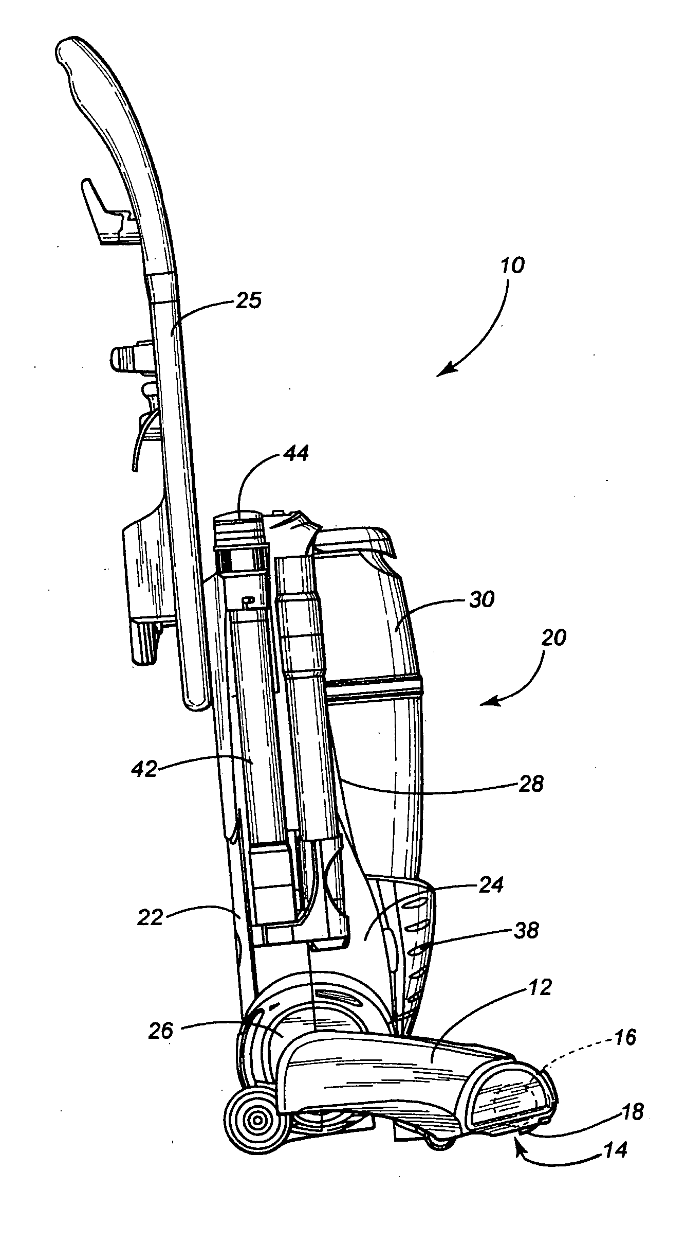
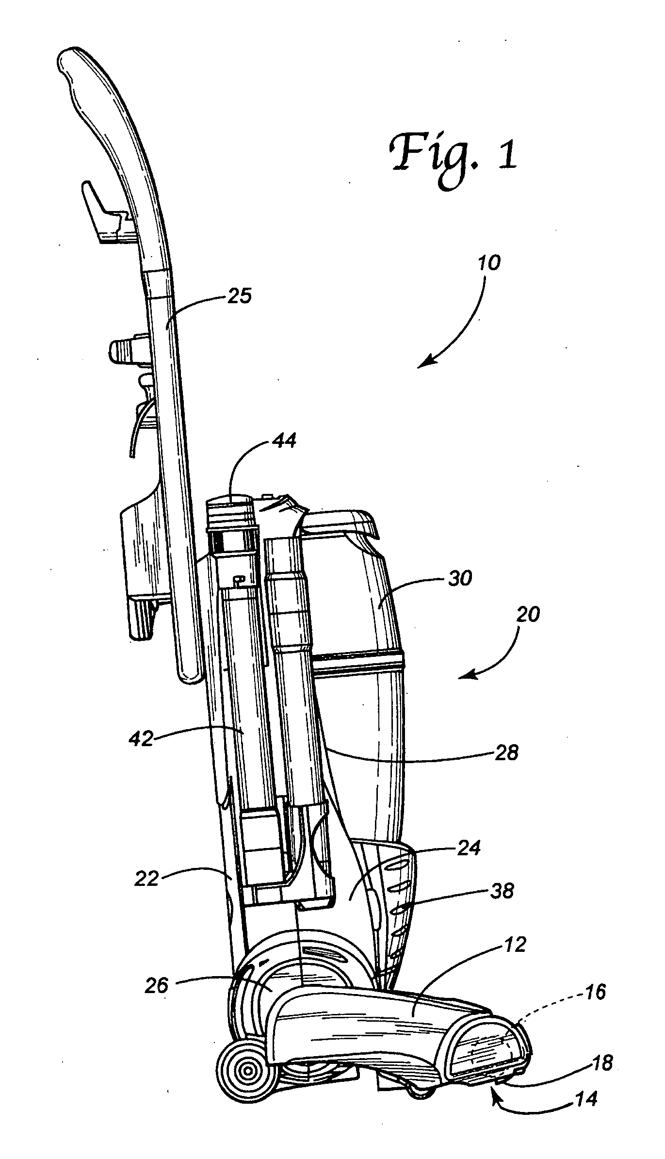
[0022] Reference is now made to FIG. 1 illustrating the floor cleaning apparatus 10 of the present invention. As illustrated the floor cleaning apparatus is an upright vacuum cleaner. It should be appreciated, however, that the present invention could also take the form of an extractor and that the upright vacuum cleaner is merely being described in detail to illustrate the principles of the present invention.

[0023] The apparatus 10 includes a nozzle assembly 12 that includes an intake opening 14. The nozzle assembly also houses a rotary agitator 16 in the intake opening 14. The rotary agitator 16 may include tufts of bristles 18 or other cleaning structures such as wipers, beater bars and brushes for brushing and beating dirt from the nap of the underlying rug or carpet being cleaned.

[0024] The apparatus 10 further includes a handle assembly, generally designated by reference numeral 20. The handle assembly 20 is pivotally connected to the nozzle assembly 12. The handle assembly ...


PUM


Abstract

An upright vacuum cleaner includes a nozzle assembly having an intake opening. A handle assembly is pivotally connected to the nozzle assembly. The vacuum cleaner also includes a suction generator and a dirt collection vessel. In addition, the vacuum cleaner includes a flexible, electrified hose such as a stretch hose.

Description

[0001] This application is a continuation of (1) U.S. patent application Ser. No. 10 / 817,561 filed on Apr. 2, 2004, which claims the benefit of U.S. Provisional Patent Application Ser. No. 60 / 460,700 filed on Apr. 4, 2003 and (2) U.S. patent application Ser. No. 10 / 870,193 filed on Jun. 17, 2004, which claims the benefit of U.S. Provisional Patent Application Ser. No. 60 / 479,131 filed on Jun. 17, 2003.TECHNICAL FIELD AND INDUSTRIAL APPLICABILITY OF THE INVENTION [0002] The present invention relates generally to the floor care equipment field and, more particularly, to a floor cleaning apparatus having a nozzle assembly for cleaning a floor, a handle assembly with control handle pivotally connected to the nozzle assembly and an electrified hose for powering a separate cleaning attachment. BACKGROUND OF THE INVENTION [0003] Upright vacuum cleaners of various shapes and designs have long been known in the art. Upright vacuum cleaners generally include a nozzle assembly having an intake...

Claims


Application Information

Patent Timeline
Patent Type & Authority Applications(United States)
IPC IPC(8): A47L5/00A47L5/32A47L9/04A47L9/24A47L9/32
CPCA47L5/225A47L5/32A47L9/04A47L9/325A47L9/24A47L9/246A47L9/0411
Inventor OVERVAAG, CHAD D.RONEY, JEFFREY T.DAVIS, RON E.BRADSHAW, AMANDA D.
Owner OVERVAAG CHAD D
Why Eureka
Try Eureka