Partially prefabricated modular foundation system

a modular foundation and prefabricated technology, applied in the field of partially prefabricated foundations, can solve the problems of compromising the structural integrity of the foundation, the risk of thermal cracking becomes very high, etc., and achieves the effects of reducing engineering work, reducing engineering work, and simplifying the permitting process

Inactive Publication Date: 2008-03-27
AHMED PHULY ENG & CONSULTING
View PDF31 Cites 74 Cited by
  • Summary
  • Abstract
  • Description
  • Claims
  • Application Information

AI Technical Summary

Benefits of technology

[0040]Another object of this invention is to provide the wind energy industry with reliable and readily available designs, and prefabricated components, for every wind energy project wherein foundation designs are pre-approved by and coordinated with turbine manufacture.
[0041]A further object of this invention is to use standard designs to reduce engineering work and simplify the permitting process, as well as improve project construction schedule.
[0042]Still another object of this invention is to utilize standard pre-approved designs resulting in significant reduction in engineering fees and third party approval fees.
[0043]It is also the object of this invention is to provide wind turbine vendors with the ability to select pre-approved complete foundation designs for wind turbine foundation based on project and site variables including turbine model and tower height; site geotechnical characteristics; and desired foundation style such as gravity or piling.
[0044]Another object of this invention is to provide foundation contractors with the convenience and economy of using commercially available prefabricated components with complete assembly and detail drawings that can be delivered to any project site with short lead time.
[0045]A further object of this invention is to improve the quality and productivity of foundation construction due to experience gained from practicing standard construction techniques.

Problems solved by technology

When concrete is cast in massive sections for wind tower foundations, temperature can reach 160 degree F. and the risk of thermal cracking becomes very high unless cooling techniques are applied.
Thermal cracking often compromises the structural integrity of the foundations.

Method used


Image

  • Partially prefabricated modular foundation system
  • Partially prefabricated modular foundation system
  • Partially prefabricated modular foundation system

Examples


Embodiment Construction

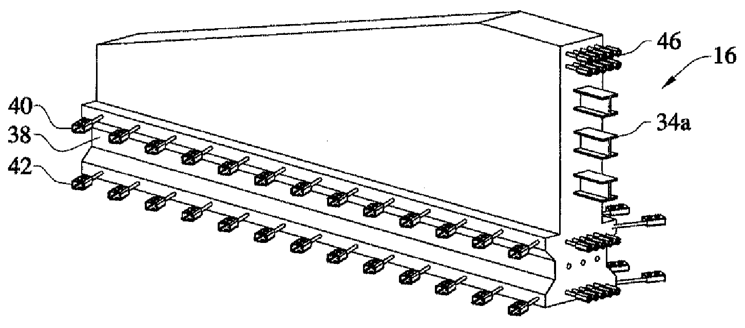
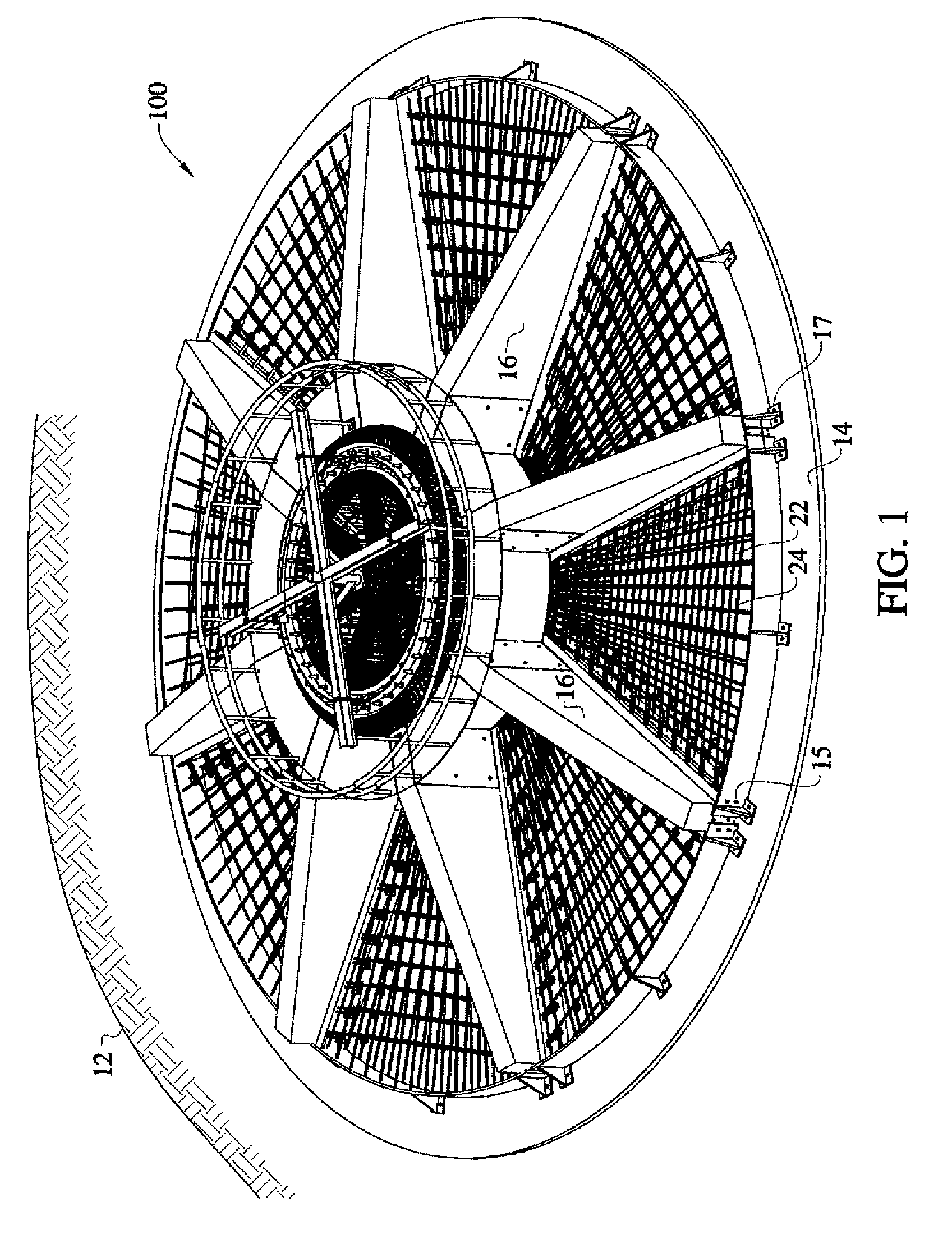
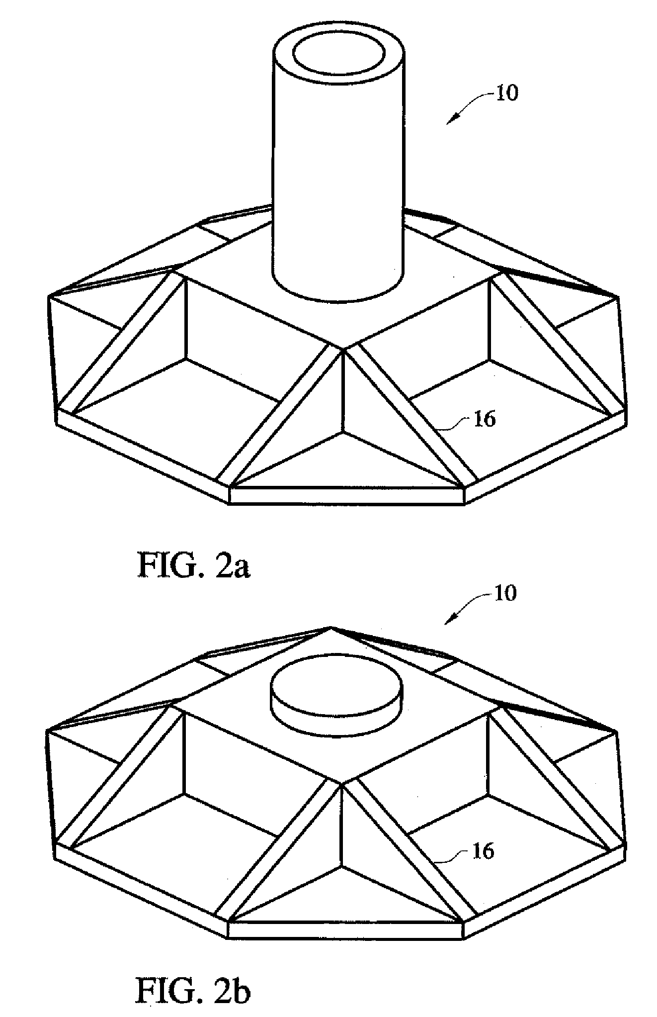
[0063]The present invention pertains to a wind turbine foundation for wind turbines. The foundation comprises a plurality of components, namely a central vertical pedestal, a substantially horizontal bottom support slab, and a plurality of radial reinforcing ribs extending radially outwardly from the pedestal. The ribs are prefabricated and transported to job site, but the pedestal and support slab are poured in situ at the site out of concrete.

[0064]A construction site is prepared by excavation and flattening and preparation of soil for the foundation 10. The foundation 10 may be set on pilings, on piers, or have anchors in a conventional manner.

[0065]The foundation 10 may be set on a mud slab 14 or on compacted granular fill. The mud slab is often a thin plain concrete layer intended to provide a clean and level base for foundation installation. After the foundation site has been prepared, a plurality of three or more precast stiffener ribs 16 are placed on the mud slab 14 or comp...


PUM

PropertyMeasurementUnit
lengthaaaaaaaaaa
widthaaaaaaaaaa
lengthaaaaaaaaaa

Abstract

A wind turbine foundation having a central pedestal, a bottom support slab, and a plurality of prefabricated radial reinforcing ribs. The pedestal and support slab are poured in situ at the site. When the concrete cures the support slab is united to the prefabricated ribs and the ribs are also united to the pedestal. The result is a continuous monolithic foundation wherein loads are carried across the structure vertically and laterally through the continuous structure by doweled and spliced reinforcing steel bars which are integrally cast into the pedestal, ribs and support slab. The slab thus behaves structurally as a continuous slab reducing deflections, improving fatigue conditions and increasing the stiffness of the foundation as well as allowing for the benefits of an economical design.

Description

BACKGROUND OF THE INVENTION[0001]1. Field of the Invention[0002]This invention relates to a method for building partially prefabricated foundations for supporting wind turbines towers.[0003]2. Description of the Related Art[0004]Conventional gravity style foundations for large wind turbine usually comprise a large, thick, horizontal, heavily reinforced cast in situ concrete base; and a vertical cast in situ cylindrical pedestal that is installed over the base. There are several problems that are typically encountered during the construction of such foundations.[0005]The main problem is the monumental task of managing large continuous concrete pours, which require sophisticated planning and coordination in order to pour more than four hundred yards of concrete in one continuous pour, without having any cold joints in.[0006]Another problem is logistics coordinating with multiple local batch plants the delivery plan of the large number of concrete trucks to the job site in a timely, or...

Claims


Application Information

Patent Timeline
Patent Type & Authority Applications(United States)
IPC IPC(8): E04H12/12E02D27/32E04G21/02
CPCE02D27/42F03D11/045Y02E10/728F05B2240/912Y02B10/30F05B2230/50F03D13/22E02D27/425E02D27/02E02D27/08E02D27/26E02B17/025E02B17/027E02B2017/006E02B2017/0069E02B2017/0073E02B2017/0091E04H12/08E04H12/16Y02P70/50Y02E10/72E04C5/04E04C5/0604E04C5/162E04C5/168E04G21/12E04H2012/006E04G21/02E04H12/341E02D27/28B28B1/14
Inventor PHULY, AHMED
Owner AHMED PHULY ENG & CONSULTING
Why Eureka
Try Eureka