Electrophotographic developing carrier, associated apparatus and methodology of classification and application

a developing carrier and a technology of electrophotography, applied in electrography/magnetography, instruments, solid separation, etc., can solve the problems of low reliability of developing carriers, high cost and low reliability of these methods, and still have to be improved, so as to achieve low cost, high quality images, and small particle diameter

Inactive Publication Date: 2008-03-27
YAMAGUCHI KIMITOSHI +2
View PDF35 Cites 16 Cited by
  • Summary
  • Abstract
  • Description
  • Claims
  • Application Information

AI Technical Summary

Benefits of technology

[0021] The present invention provides a carrier having a small particle diameter at low cost, which produces high quality images, and which has less adherence and a focused particle diameter distribution. Exemplary embodiments of the invention provide a classifier classifying the carrier, a method of classifying the carrier, a method of preparing the carrier, a developer using the carrier, and a process cartridge using the developer.

Problems solved by technology

However, the high costs and low reliability of these method are still to be improved.
However, a developer including such a toner still poses difficulties, such as background fouling and insufficient image density.
However, conventional carries having a small particle diameter tend to adhere to photoreceptors and fixing rollers, and have problems in practical application.
However, the classification method using a sieve is known to have a difficulty in making the particle diameter distribution of particles having a small mass narrow.
However, when a sieve has a mesh having small openings, since a mesh material is thin and a strength of the mesh is small (a thread is thin), an edge of the mesh is broken due to a weight of the carrier after used for a longtime.
When the mesh is clogged, the carrier hide among openings and it is quite difficult to remove the carrier, resulting in a need to replace the mesh.
Since the resin thread has a small stiffness, an ultrasound is not effectively transmitted to the mesh to classify.
On the other hand, production costs of a stainless mesh having small openings are extremely high, resulting in higher production costs of the carrier.

Method used


Image

  • Electrophotographic developing carrier, associated apparatus and methodology of classification and application
  • Electrophotographic developing carrier, associated apparatus and methodology of classification and application
  • Electrophotographic developing carrier, associated apparatus and methodology of classification and application

Examples


preparation example 1

Carrier Preparation Example 1

[0109] In silicone resin (SR2411 from Dow Corning Toray Silicone Co., Ltd., of Chiyoda-ku, Tokyo, Japan), carbon (KETJENBLACK EC-600JD from Lion Corp., of Sumida-ku, Tokyo, Japan) of 7% per 100% of a solid content of the silicone resin was dispersed for 60 min by a ball mill. The dispersion was diluted to prepare a dispersion having a solid content of 5%.

[0110] Further, an amino silane coupling agent (NH2(CH2)3Si(OCH3)) of 3% per 100% of the solid content of the silicone resin was mixed with the dispersion to prepare a dispersion.

[0111] The dispersion was coated on 5 kgs of a carrier core material I in Table 1 by a fluidized bed coater at 30 g / min in an atmosphere of 100° C., and was further heated at 200° C. for 2 hrs to prepare a resin-coated carrier A having a resin layer thickness of 0.31 μm. The resin layer thickness was controlled by an amount of the coating liquid, i.e., the dispersion.

[0112] The particle diameter distribution of the carrier A ...

preparation example 2

Carrier Preparation Example 2

[0113] The carrier core material I in Table 1 was fed onto a stainless mesh at 0.5 Kgs / min to classify the carrier core material I.

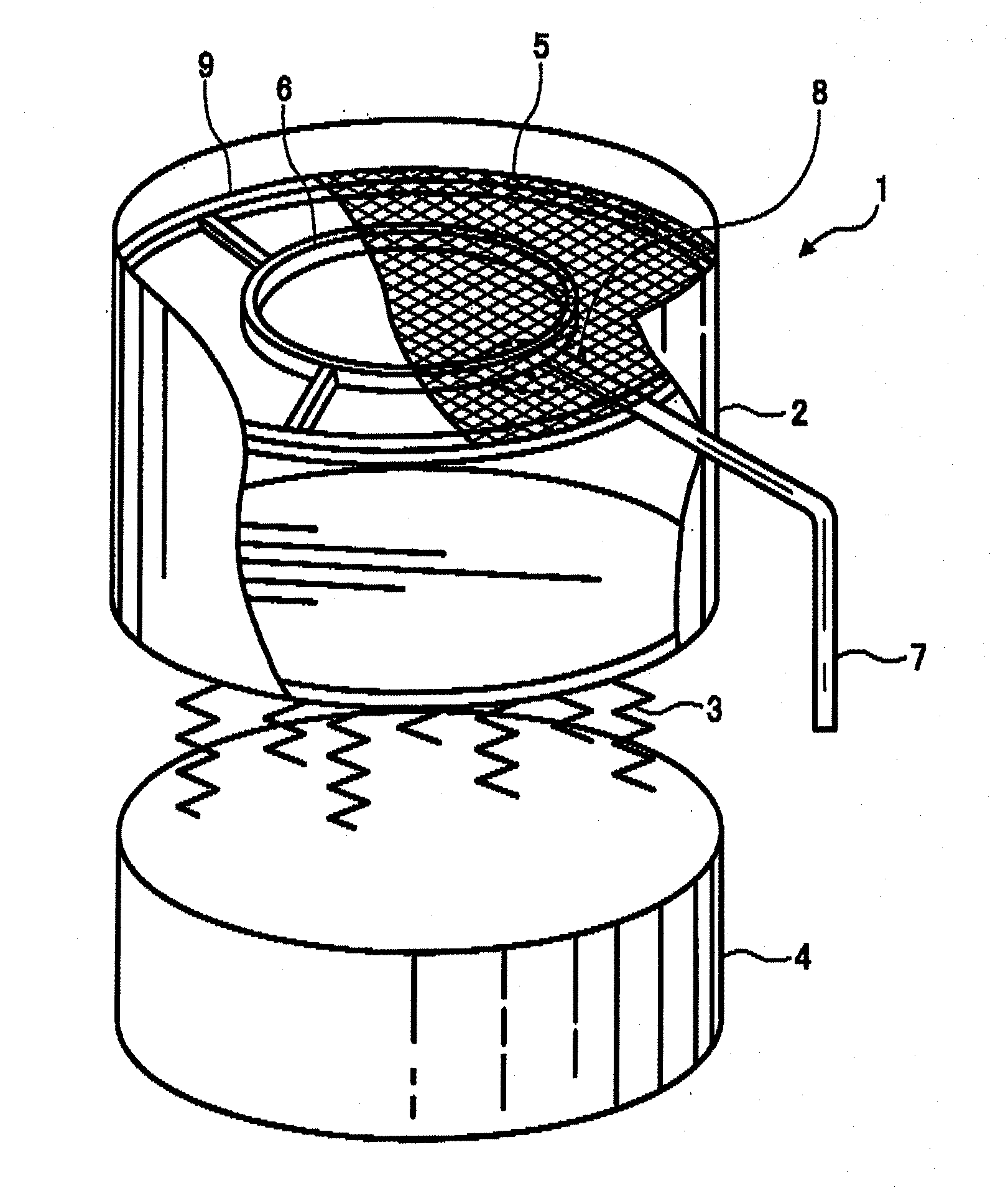
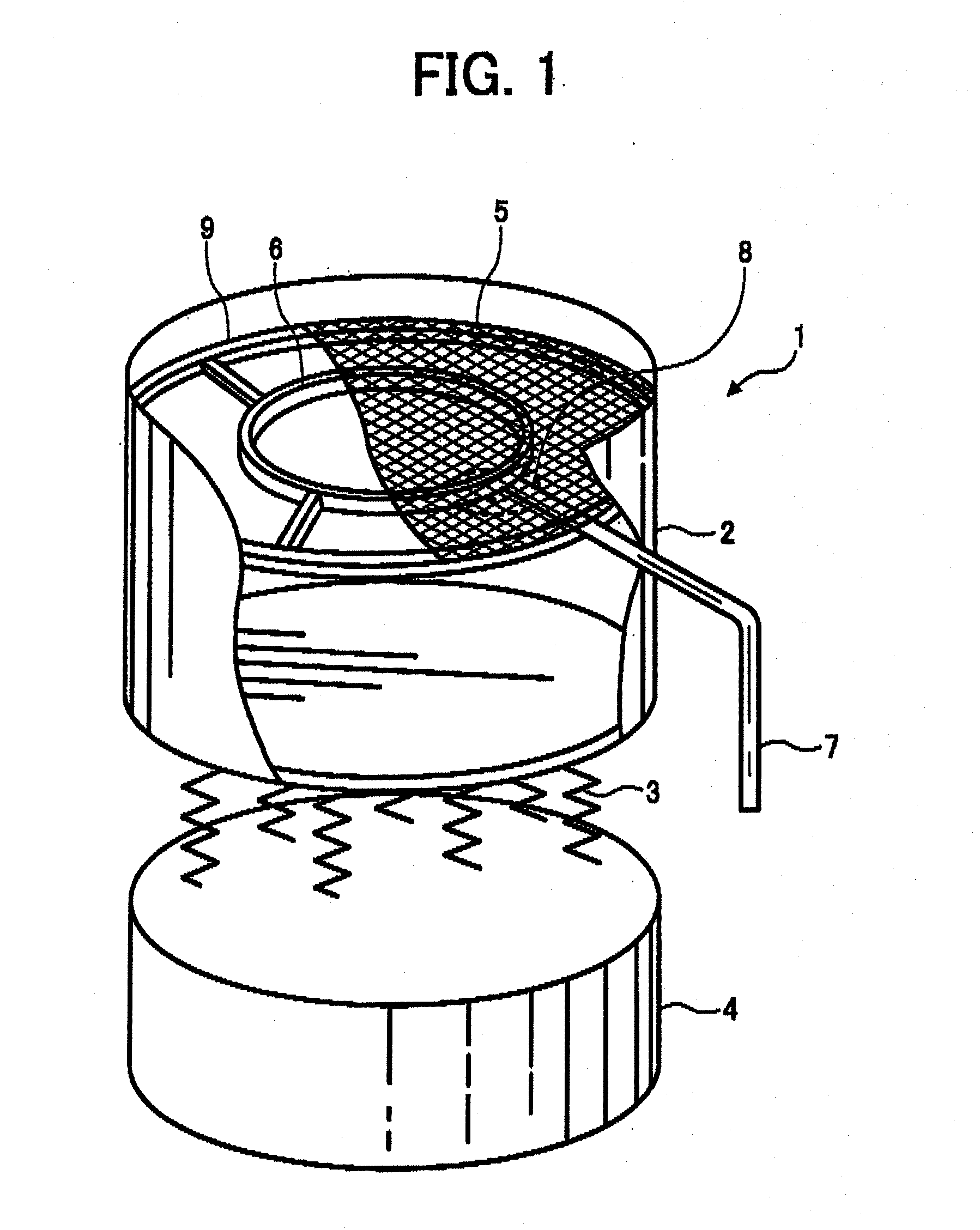
[0114] A vibrating sieve used has a constitution in FIG. 1 and is a sieving apparatus 1, wherein a resonant ring 6 having a transducer 8 generating an ultrasonic wave having a frequency of 36 kHz as a resonant member is directly contacts a stainless mesh 5 (635 mesh / single) having a diameter of 70 cm, supported by a frame 9.

[0115] The stainless mesh 5 is located in a cylindrical container 2 supported by a base 4 through a spring 3. A vibration motor (not shown) is located in the base 4, which transmits a high-frequency current to the transducer 8 installed at the resonant ring 6 through a cable 7 to generate the ultrasonic wave.

[0116] The resonant ring 6 is vibrated by the ultrasonic wave, which vertically vibrates the whole mesh 5. The carrier core material fed onto the stainless mesh 5 in the cylindrical container 2 is s...

preparation example 3

Carrier Preparation Example 3

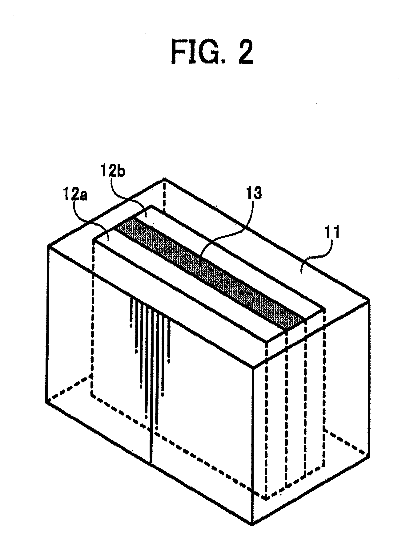
[0124] In the vibrating sieve in FIG. 1, a stainless mesh having openings of 104 μm (150 mesh) was located underneath, and a nylon mesh having openings of 20 μm was closely layered thereon. A material (nylon-66) used for the nylon mesh has a flexural modulus of 2.8 Gpa.

[0125] The stainless mesh underneath directly receives a vibration from the ultrasonic transducer, and the ultrasonic vibration is efficiently transmitted to the nylon mesh closely located thereon and the nylon mesh classifies the particles.

[0126] The carrier core material I in Table 1 was fed onto the nylon mesh at 0.5 Kgs / min to classify the carrier core material I using the vibration sieve just as classified in Carrier Preparation Example 2 to prepare a carrier core material III.

[0127] As a result of the classification, a ratio of the carrier core material having a particle diameter less than 22 μm could largely be reduced. The particle diameter distribution the carrier core material...


PUM


Abstract

A vibrating sieve for classifying a particulate material, including an oscillator comprising a transducer; and at least two meshes layered together and located in contacting relation to a transducer, wherein a lowermost mesh receiving a vibration from the transducer transmits the vibration to an uppermost mesh to classify the particulate material fed thereon.

Description

CROSS-REFERENCE TO RELATED APPLICATIONS [0001] This application is a Division of and is based upon and claims the benefit of priority under 35 U.S.C. §120 for U.S. Ser. No. 10 / 977,013, filed Nov. 1, 2004, and claims the benefit of priority under 35 U.S.C. §119 from Japanese Patent Application No. 2003-388599, filed Nov. 18, 2003, and Japanese Patent Application No. 2004-206102, filed Jul. 13, 2004, the entire contents of each which are incorporated herein by reference.BACKGROUND OF THE INVENTION [0002] The present invention relates to a carrier, a classifier for classifying the carrier, a method of classifying the carrier, a method of preparing the carrier, a developer using the carrier and a process cartridge using the developer. [0003] Electrophotographic developing methods include a one-component developing method using only a toner, and, a two-component developing method using a two-component developer including a carrier and a toner. [0004] The carrier in the two-component deve...

Claims


Application Information

Patent Timeline
Patent Type & Authority Applications(United States)
IPC IPC(8): B07B1/28B07B1/42G03G9/10
CPCG03G9/10B07B1/42B07B2230/04
Inventor YAMAGUCHI, KIMITOSHINAGAYAMA, MASASHIIMAHASHI, NAOKI
Owner YAMAGUCHI KIMITOSHI
Why Eureka
Try Eureka