Contactor assembly with arc steering system

a technology of arc steering system and contactor, which is applied in the direction of circuit-breaking switches, magnetic bodies, magnets, etc., can solve the problems of irregularities, contact welding, and detrimental to the life of the contactor as well as the continued operability of the contactor, so as to promote the movement of the arc, and increase the strength of the magnetic field

Active Publication Date: 2008-03-27
ROCKWELL AUTOMATION TECH
View PDF44 Cites 26 Cited by
  • Summary
  • Abstract
  • Description
  • Claims
  • Application Information

AI Technical Summary

Benefits of technology

[0009]The present invention provides a contactor having a magnetic field intensifier that, rather that encasing the slot motor magnet in an insulator and moving it away from the arc, moves the magnetic field intensifying structure closer to the arc by extending a magnetically reactive arm along a side of the contact. The arm is designed to attract the arc and to promote movement of the arc toward the suppressor. A combination of the shape of the arm to promote arc movement and the increased strength of the magnetic field provided by the arm, serves to minimize arc damage to the contact.
[0010]Specifically then, the present invention provides a switch assembly that includes a stationary contact, an arc contact, an arc arrestor, and a magnetic intensifier. The magnetic intensifier is constructed to be positioned in generally close proximity to one of the contacts of the switch assembly. During communication of power through the contactor assembly, the magnetic intensifier accentuates a magnetic field generated by a current passed through a turnback of one of the contacts and increases the magnitude of a magnetic force directed toward the arc arrestor. In one embodiment, the magnetic intensifier is formed as a pair of arms that extend from the turnback in close proximity to contact. Preferably, the intensifier and turnback are formed from a continuous piece of copper clad steel.
[0013]A further aspect of the invention discloses a method of manufacturing a switch assembly. The method includes cutting a body from a metallic material. A turnback is formed by folding the body along a first fold line such that a first portion of the body overlies a second portion of the body. The body is folded along second and third fold lines that are oriented in crossing directions with the first fold line such that the turnback is flanked by a pair of arc rails which extend in a direction away from an area bound by the first and second portions of the body. The arc rails intensify the magnetic field associated with a current passing through the turnback. Such a construction simplifies the construction and assembly of the switch.

Problems solved by technology

Prolonged arcing between the contacts can damage the mating surfaces of the contacts, can damage structures adjacent the contactor, and / or can result in the welding together of the contacts.
Arc damage to the mating surfaces of the contacts detrimentally affects the life of the contactor as well as the continued operability of the contactor.
Irregularities in the surface of the contacts caused by arc damage results in contacts that do not fully close in a coplanar manner and in separations between the current carrying surfaces of the contacts when the contacts are closed.
Arcing can also cause irregularities that protrude above the preferably planar mating surfaces of the contacts.
These irregularities tend to attract subsequent circuit termination arcs that further degrade the mating surface of the contact.
Accordingly, although such an arc arrestor aims to quickly quench a circuit termination arc, such arc arrestors inadequately address expedient transfer of the arc away from the contacts.
Such magnetic intensifiers occasionally result in the arc being attracted to the conductive material of the slot motor magnet damaging the slot motor assembly and possibly delaying movement of the arc away from the contacts.
Unfortunately, such modification increases the distance between the slot motor magnetic material and the contactor thereby reducing the magnitude of the magnetic force associated with the slot motor magnet.
Accordingly, although such a modification minimizes the potential of arc attraction with the conductive material of the slot motor magnet, such modification also detrimentally affects the desired magnetic effect of the slot motor magnet.

Method used


Image

  • Contactor assembly with arc steering system
  • Contactor assembly with arc steering system
  • Contactor assembly with arc steering system

Examples


Embodiment Construction

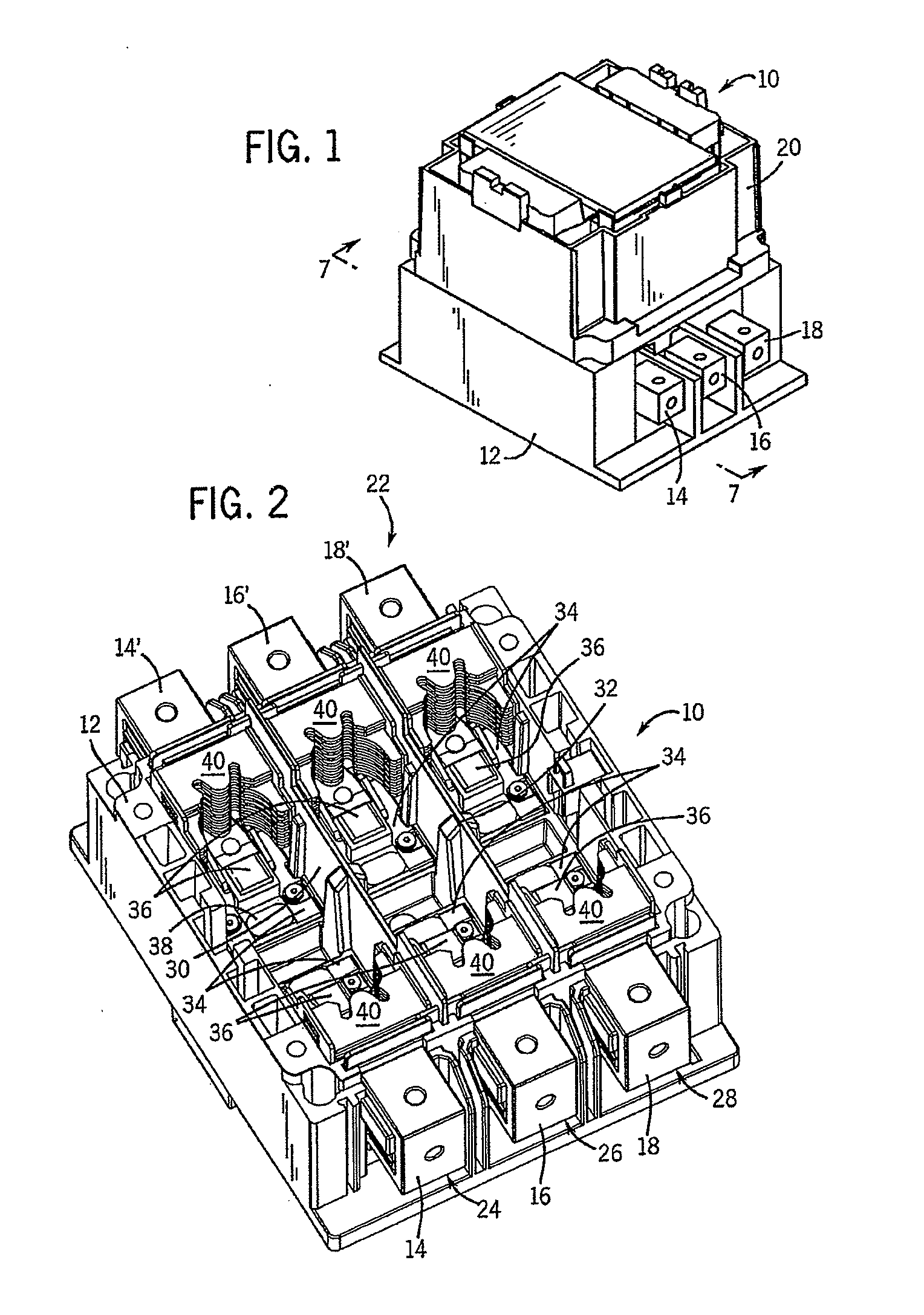
[0028]FIG. 1 shows an exemplary circuit interrupter or contactor assembly 10 according to the present invention. Contactor assembly 10 includes a housing 12 having a plurality of connections 14, 14′, 16, 16′, 18, and 18′ passing therethrough. Understandably, it is appreciated that, as shown, contactor assembly 10 is configured as a three-phase contactor assembly and that other contactor assembly configurations, such as single phase, are envisioned and within the scope of the claims. It is recognized that the present invention is applicable for contactor assemblies having one contactor to a plurality of contactors, including more than three.

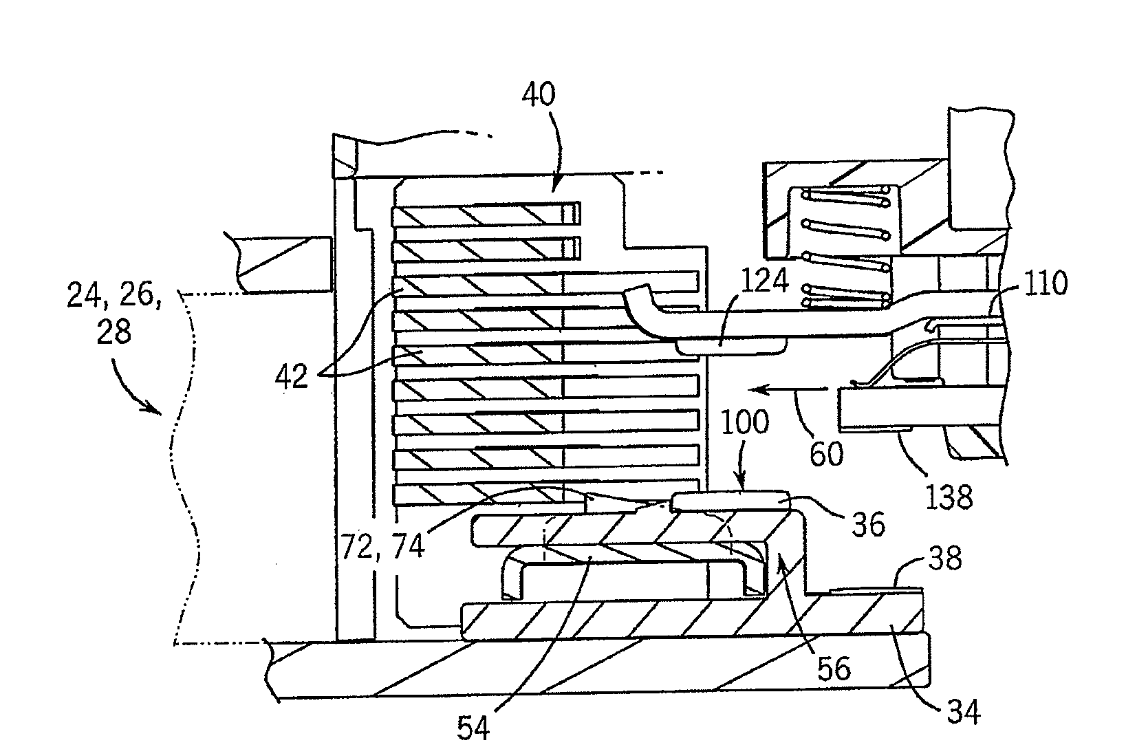
[0029]Cover 20 is constructed to engage housing 12 and generally encloses the electrical componentry disposed therebehind. As shown in FIG. 2, removing cover 20 from housing 12 exposes a fixed portion 22 of a plurality of severable electrical circuits 24, 26, 28 between connectors 14, 14′; 16, 16′ and 18, 18′. Housing 12 includes a plurality of up...


PUM

PropertyMeasurementUnit
currentaaaaaaaaaa
magnetic fluxaaaaaaaaaa
magneticaaaaaaaaaa

Abstract

A contactor assembly includes a stationary contact, an arc contact, an arc arrestor, and a magnetic intensifier. The magnetic intensifier is constructed to extend in generally close proximity to one of the stationary contact and the arc contact. During communication of power through the contactor assembly, the magnetic intensifier manipulates a magnetic field associated with current passing through the contactor assembly and increases the magnitude of a magnetic force directed to the arc arrestor. Preferably, the magnetic intensifier is formed integrally with a turnback associated with one of the stationary contact or the arc contact. Such a construction simplifies the manufacture and assembly of the contactor assembly and provides efficient and repeatable arc suppression.

Description

CROSS-REFERENCE TO RELATED APPLICATIONS[0001]This application is a continuation-in-part of U.S. patent application Ser. No. 11 / 526,040 filed on Sep. 22, 2006 titled “Contactor Assembly with Arc Steering System” and the disclosure of which is incorporated herein.BACKGROUND OF THE INVENTION[0002]The present invention is directed to electrical contactors and, more particularly, to an arc steering system for such contactors.[0003]A contactor or circuit breaker is a type of current interrupting switch or severable electrical connection that is capable of substantially limiting the duration and the intensity of current flowing in a circuit experiencing a short circuit fault. Other severable electrical connections are commonly referred to as relays, disconnects, circuit breakers, switches, safety switches, enclosed circuit breakers, power circuit breakers, current-limiting circuit breakers, ground fault circuit breakers (GFCI's), and arc fault circuit interrupters (AFCI's). Understandably,...

Claims


Application Information

Patent Timeline
Patent Type & Authority Applications(United States)
IPC IPC(8): H01H9/44
CPCH01H9/36Y10T29/49105Y10T29/4902H01H9/446H01H9/38
Inventor ANNIS, JEFFREY RAMSEYDUCHROW, ROBERT ALFREDBENEKE, SUSAN L.MILLER, JAMES PETER
Owner ROCKWELL AUTOMATION TECH
Why Eureka
Try Eureka