Circuit and method for driving light source

Inactive Publication Date: 2008-03-27
BEYOND INNOVATION TECH
View PDF8 Cites 16 Cited by
  • Summary
  • Abstract
  • Description
  • Claims
  • Application Information

AI Technical Summary

Benefits of technology

[0010]The present invention further provides a driving method for a light source to provide efficient heat dissipation for a LED.
[0011]The driving circuit in the present invention is suitable for a light source having a plurality of LEDs. The circuit includes a first PWM unit and a power conversion unit. The fir

Problems solved by technology

However, heat radiation has been the one major problem which affects the performance of a LED.
Even though the structure illustrated in FIG. 1 can dissipate the heat generated during the operation of the LED module 100, however, the spee

Method used


Image

  • Circuit and method for driving light source
  • Circuit and method for driving light source
  • Circuit and method for driving light source

Examples


Embodiment Construction

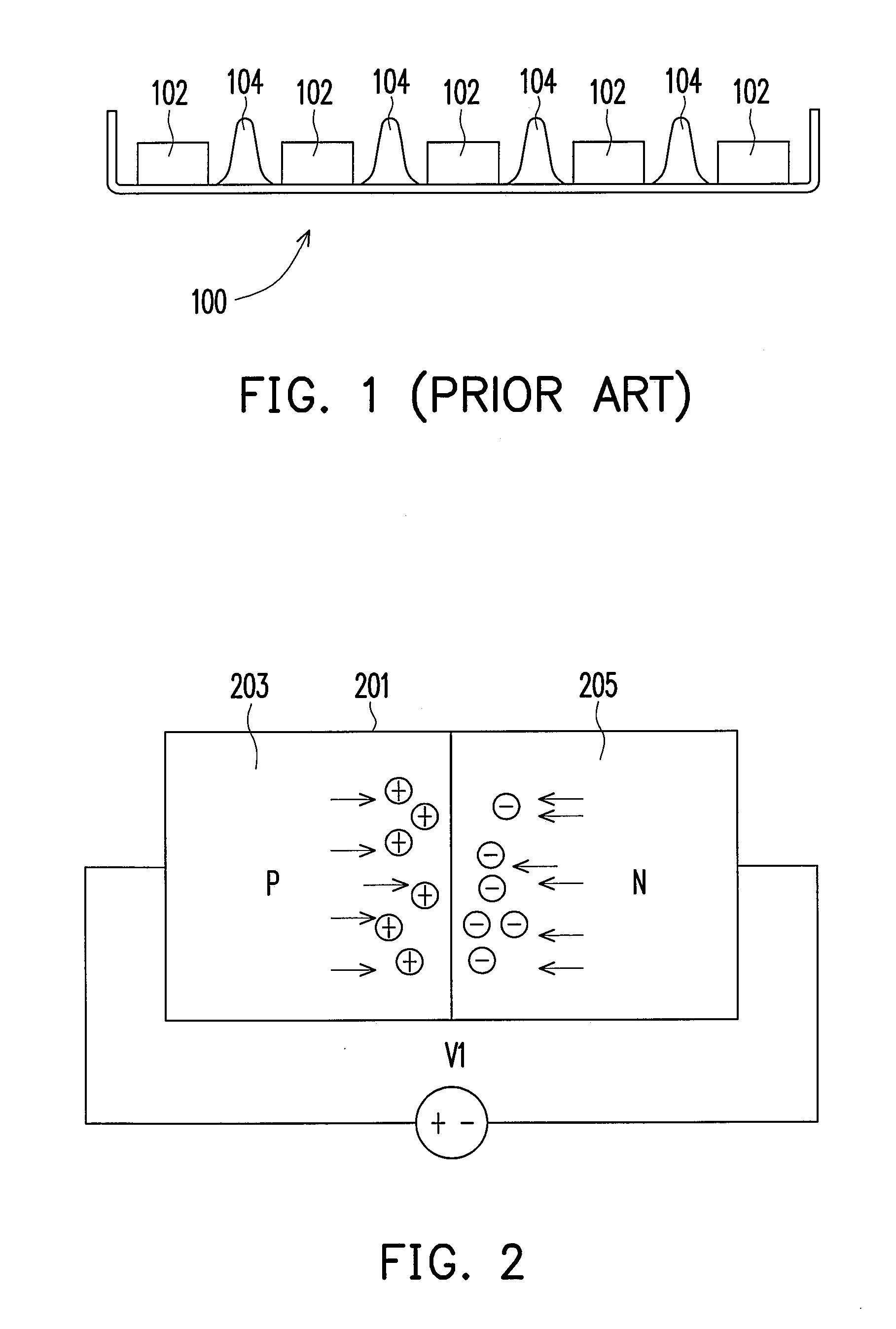
[0029]Referring to FIG. 2, a light emitting diode (LED) is a semiconductor with PN junction and it emits light when it is supplied with a forward bias. As shown in FIG. 2, the LED 201 has a P-region 203 and an N-region 205. When a DC forward bias V1 is supplied to the LED 201, holes in P-region 203 and electrons in N-region 205 move towards the PN junction and re-combine randomly, and at this time, energy is released. The description above shows the light emitting theory of LED.

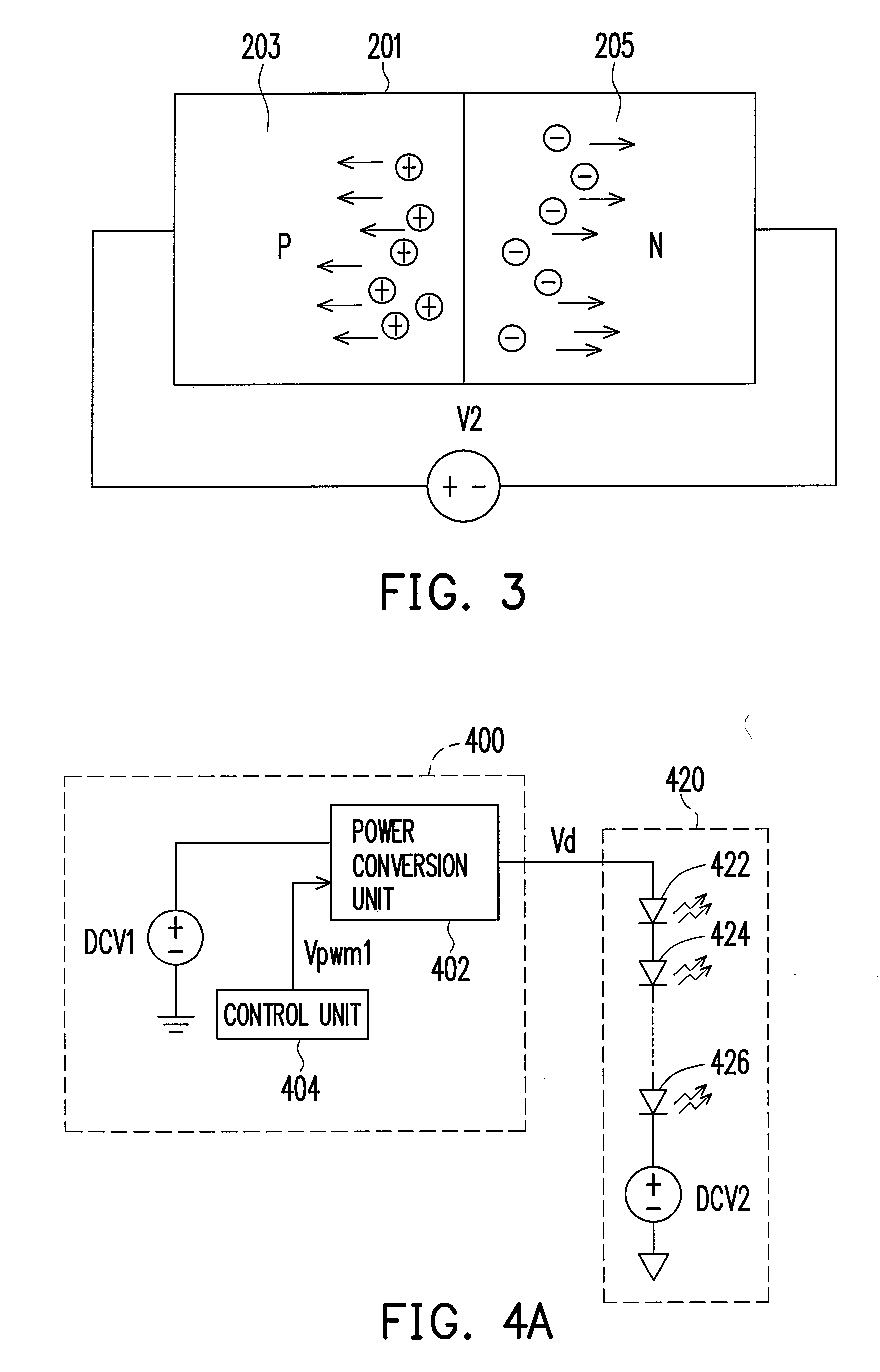
[0030]When a LED is working, since energy is released due to re-combination of electrons and holes, the temperature at the PN junction of the LED increases. On the other hand, when the LED is working under a reversed bias, as shown in FIG. 3, a reversed bias V2 is supplied to the LED 201, holes in P-region 203 and electrons in N-region 205 leave the PN junction and move towards two ends of the LED 201. The heat energy at the PN junction of the LED is carried to the two ends of the LED through the movement of ...


PUM


Abstract

A driving circuit for a light source is provided. The circuit is suitable for a light source with a plurality of light emitting diodes (LED). The circuit includes a first pulse width modulation (PWM) unit and a power conversion unit. The first PWM unit generates a first PWM signal. The power conversion unit generates a driving voltage signal for controlling the light source to perform forward bias operation or reversed bias operation according to the duty cycle of the first PWM signal.

Description

CROSS-REFERENCE TO RELATED APPLICATION[0001]This application claims the priority benefit of Taiwan application serial no. 95134927, filed Sep. 21, 2006. All disclosure of the Taiwan application is incorporated herein by reference.BACKGROUND OF THE INVENTION[0002]1. Field of the Invention[0003]The present invention relates to a driving circuit and a method thereof. More particularly, the present invention relates to a driving circuit capable of maintaining the operation temperature of at a light emitting diode (LED) and a method thereof.[0004]2. Description of Related Art[0005]Light emitting diode (LED) is a semiconductor device which is fabricated with semiconductor material of the III-V groups of elements compound. Such semiconductor material has the electricity / light conversion characteristics. More specifically, when a current is supplied to such semiconductor material, electrons and holes in the material combine and release excess energy as light to achieve light emitting effect...

Claims


Application Information

Patent Timeline
IPC IPC(8): H05B39/04
CPCH05B33/0815Y02B20/346H05B33/0854H05B33/0818H05B45/18H05B45/3725Y02B20/30
Inventor CHEN, LEAFKAO, CHIN-FA
Owner BEYOND INNOVATION TECH
Why Eureka
Try Eureka