Resistivity tools with collocated antennas

a technology of resistivity tools and antennas, applied in the field of resistivity well logging tools and methods, can solve the problems of extremely long tools and inability to provide anisotropy information for antennas, and achieve the effect of improving the sensitivity of the antenna and high magnetic permeability

Active Publication Date: 2008-03-27
BAKER HUGHES INC
View PDF24 Cites 67 Cited by
  • Summary
  • Abstract
  • Description
  • Claims
  • Application Information

AI Technical Summary

Benefits of technology

[0010]In one aspect, the tool member may be a conductive member, such as a drill collar or a metallic sleeve placed around a drill collar or another tool body or it may be a longitudinal member associated with a wireline tool. Any of the collocated antennas may be an axial antenna, transverse antenna or an antenna with another suitable orientation. An axial antenna may include a plurality of axial slots or grooves made on a tool member and at least one electrical conductor, such as a wire, placed over the plurality of slots to form a loop antenna. A suitable high magnetic permeability material, such as ferrite, ma

Problems solved by technology

These antennas do not provide information relating to anisotropy at low relative dipping angles and direction of an approaching bed relative

Method used


Image

  • Resistivity tools with collocated antennas
  • Resistivity tools with collocated antennas
  • Resistivity tools with collocated antennas

Examples


Embodiment Construction

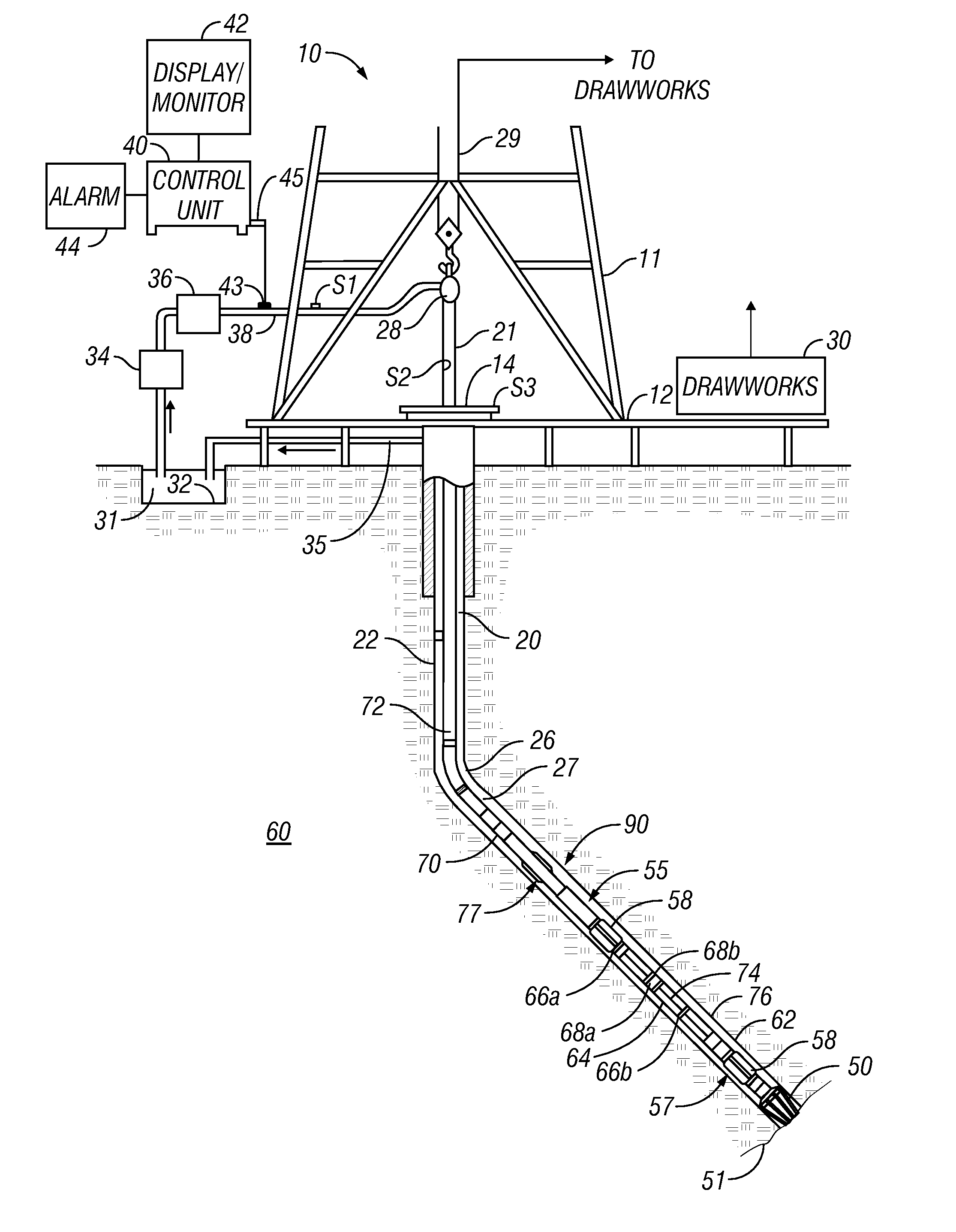
[0033]FIG. 1 shows a schematic diagram of a drilling system 10 that includes a drill string 20 having a drilling assembly 90, also referred to as a bottomhole assembly (BHA) for drilling a borehole 26 (also referred to as a wellbore) in an earth formation 60. The drilling system 10 is shown to include a conventional derrick 11 erected on a floor 12 that supports a rotary table 14 that is rotated by a prime mover, such as an electric motor (not shown), at a desired rotational speed. The drill string 20 includes a drilling tubula, 22 such as a drill pipe extending downward from the rotary table 14 into the borehole 26. A drill bit 50 attached to the end of the BHA 90 disintegrates the geological formations when it is rotated to form the borehole 26. The drill string 20 is coupled to a drawworks 30 via a kelly joint 21, swivel 28 and a line 29. During the drilling operations drawworks 30 is operated to control the weight on bit, which is a parameter that affects the rate of penetration...


PUM


Abstract

The disclosure provides a resistivity tool for use in a wellbore, wherein at least two antennas are located at the same or substantially the same location of the tool. Each antenna may be configured to operate as a transmitter or receiver.

Description

CROSS-REFERENCE TO RELATED APPLICATIONS[0001]This application takes priority from U.S. Provisional Patent Application No. 60 / 846,949, filed on Sep. 25, 2006, which is fully incorporated herein by reference.BACKGROUND OF THE DISCLOSURE[0002]1. Field of the Disclosure[0003]This disclosure herein relates to the field of electrical resistivity well logging tools and methods.[0004]2. Description of the Related Art[0005]Wellbores or boreholes for producing hydrocarbons (such as oil and gas) are drilled using a drill string that includes a tubing made up of jointed tubulars or a continuous coiled tubing with a drilling assembly, also referred to as the bottom hole assembly (BHA), attached to its bottom end. The BHA includes a number of sensors, formation evaluation tools, and directional drilling tools. A drill bit attached to the BHA is rotated with a drilling motor in the BHA and / or by rotating the drill string to drill the wellbore. One of the formation evaluation tools commonly used is...

Claims


Application Information

Patent Timeline
IPC IPC(8): H01Q1/04
CPCG01V3/28H01Q25/00H01Q7/06H01Q1/04
Inventor SIGNORELLI, JACKWANG, TSILI
Owner BAKER HUGHES INC
Why Eureka
Try Eureka