Method of rendering pixel-composited images for a graphics-based application running on a computing system embodying a multi-mode parallel graphics rendering system

a graphics-based application and computing system technology, applied in image generation, instruments, architectures with multiple processing units, etc., can solve problems such as slowing down the working rate of the graphics system

Inactive Publication Date: 2008-03-27
GOOGLE LLC +1
View PDF99 Cites 17 Cited by
  • Summary
  • Abstract
  • Description
  • Claims
  • Application Information

AI Technical Summary

Benefits of technology

[0034] As illustrated in FIG. 3B, the Object Division (Sort-Last) Method of Parallel Graphics Rendering decomposes the 3D scene (i.e. rendered database) and distributes graphics display list data and commands associated with a portion of the scene to the particular graphics pipeline (i.e. rendering unit), and recombines the partially rendered pixel frames, during recomposition. The geometric database is therefore shared among GPUs, reducing the load on the geometry buffer, the geometry subsystem, and even to some extent, the pixel subsystem. The main concern is how to divide the data in order to keep load balance. An exemplary multiple-GPU platform of FIG. 3B for supporting the object-division method is shown in FIG. 3A. The platform requires complex and costly pixel compositing hardware which prevents its current application in a modern PC-based computer architecture.
[0035] Today, real-time graphics applications, such as advanced video games, are more demanding than ever, utilizing massive textures, abundance of polygons, high depth-complexity, anti-aliasing, multi-pass rendering, etc., with such robustness growing exponentially over time.

Problems solved by technology

This, in turn, causes both computational and buffer contention challenges which slow down the working rate of the graphics system.

Method used


Image

  • Method of rendering pixel-composited images for a graphics-based application running on a computing system embodying a multi-mode parallel graphics rendering system
  • Method of rendering pixel-composited images for a graphics-based application running on a computing system embodying a multi-mode parallel graphics rendering system
  • Method of rendering pixel-composited images for a graphics-based application running on a computing system embodying a multi-mode parallel graphics rendering system

Examples


Embodiment Construction

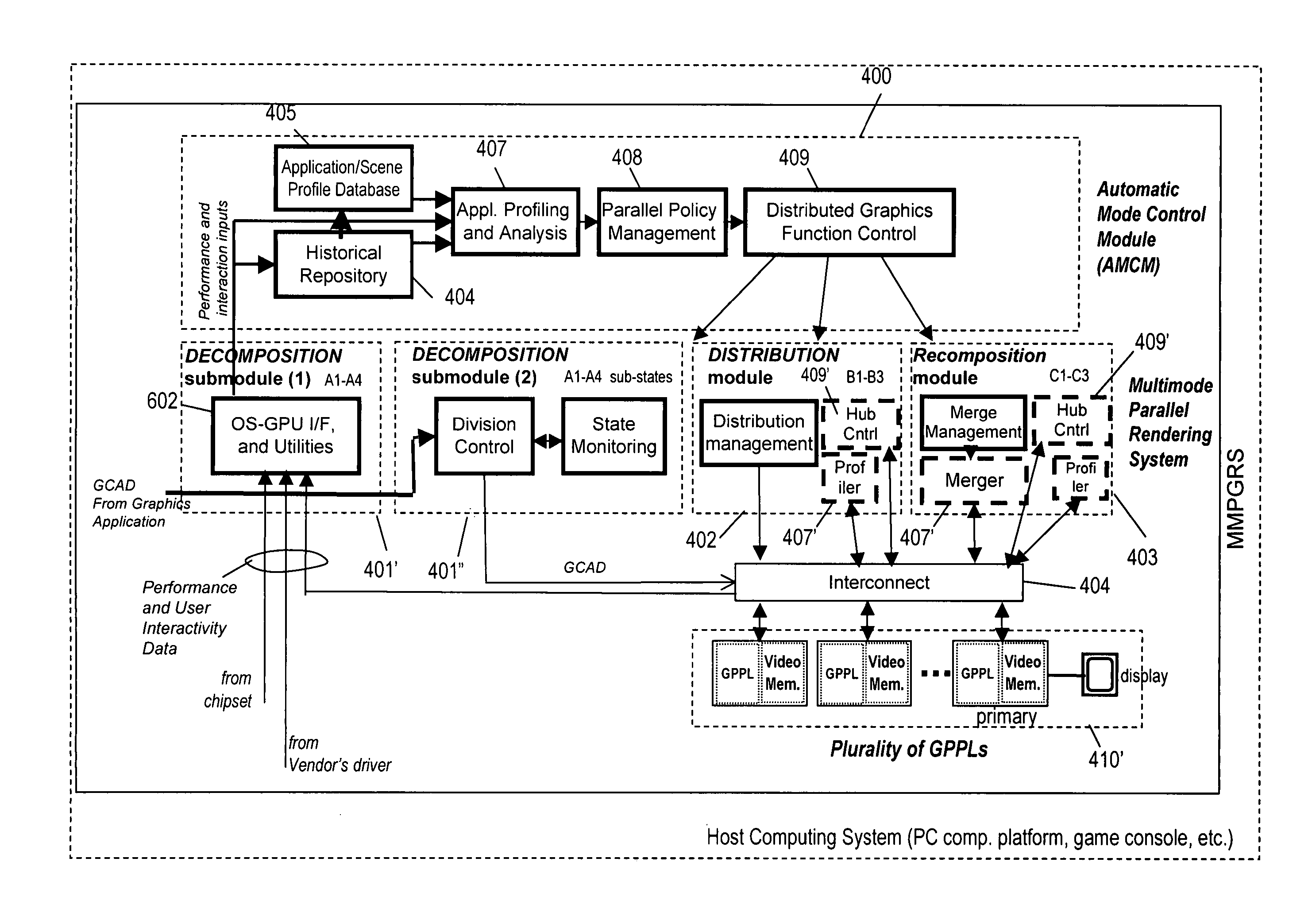
[0217] Referring now to FIGS. 4A through 12B in the accompanying Drawings, the various illustrative embodiments of the Multi-Mode Parallel Graphics Rendering System (MMPGRS) and Multi-Mode Parallel Graphics Rendering Process (MMPGRP) of the present invention will now be described in great technical detail, wherein like elements will be indicated using like reference numerals.

[0218] In general, one aspect of the present invention teaches how to dynamically retain high and steady performance of a three-dimensional (3D) graphics system on conventional platforms (e.g. PCs, laptops, servers, etc.), as well as on silicon level graphics systems (e.g. graphics system on chip (SOC) implementations, integrated graphics device IGD implementations, and hybrid CPU / GPU die implementations). This aspect of the present invention is accomplished by means of a novel architecture supporting adaptive graphics parallelism having both software, hardware and hybrid embodiments.

[0219] The MMPGRS and MMPG...


PUM


Abstract

A method of rendering pixel-composited images for a graphics-based application running on a computing system embodying a multi-mode parallel graphics rendering system (MMPGRS). The MMPGRS includes a plurality of graphic processing pipelines (GPPLs) supporting a parallel graphics rendering process employing one or more modes of parallel operation selected from the group consisting of object division, image division, and time division. Each mode of parallel operation has decomposition, distribution and recomposition stages. The MMPGRS employs one or more modes of said parallel operation in order to execute graphic commands, and process graphics data, and render pixel-composited images containing graphics for display on a display device during the run-time of said graphics-based application. The MMPGRS further includes a primary GPPL and at least one secondary GPPL, and wherein each GPPL includes (i) a GPU having a geometry processing subsystem provided with a programmable vertex shader, and a pixel processing subsystem provided with a programmable fragment shader, and (ii) video memory including a frame buffer (FB) having depth and color frame buffers for buffering pixel depth and color value, respectively. During the recomposition stage of the object division mode, the pixel depth and color values are moved from the frame buffers in the secondary GPPL, to the frame buffers in the primary GPPL, by way of inter-GPPL communication, and thereafter, the pixel depth and color values are merged with their counterparts, within the frame buffer of the primary GPPL, using the programmable vertex shader provided in the geometry processing subsystem and / or the programmable fragment shader provided in the pixel processing subsystem.

Description

CROSS-REFERENCE TO RELATED CASES [0001] The present application is a Continuation of U.S. application Ser. No. 11 / 897,536 filed Aug. 30, 2007; which is a Continuation-in-Part (CIP) of the following Applications: U.S. application Ser. No. 11 / 789,039 filed Apr. 23, 2007; U.S. application Ser. No. 11 / 655,735 filed Jan. 18, 2007, which is based on Provisional Application Ser. No. 60 / 759,608 filed Jan. 18, 2006; U.S. application Ser. No. 11 / 648,160 filed Dec. 31, 2006; U.S. application Ser. No. 11 / 386,454 filed Mar. 22, 2006; U.S. application Ser. No. 11 / 340,402 filed Jan. 25, 2006, which is based on Provisional Application No. 60 / 647,146 filed Jan. 25, 2005; U.S. application Ser. No. 10 / 579,682 filed May 17, 2006, which is a National Stage Entry of International Application No. PCT / IL2004 / 001069 filed Nov. 19, 2004, which is based on Provisional Application Ser. No. 60 / 523,084 filed Nov. 19, 2003; each said patent application being commonly owned by Lucid Information Technology, Ltd., a...

Claims


Application Information

Patent Timeline
Patent Type & Authority Applications(United States)
IPC IPC(8): G06F15/80G06F15/16G06T1/20G06T15/00
CPCG06F9/5044G06T1/20G06F2209/501G06T2210/52G06T15/005
Inventor BAKALASH, REUVENLEVIATHAN, YANIV
Owner GOOGLE LLC
Why Eureka
Try Eureka