Communication System, Communication Apparatus, and Electric-Field-Coupling Antenna

a communication system and antenna technology, applied in the field of communication systems, can solve the problems of difficult suppression of the electric field generated therein, and interference of neighboring communication systems,

Active Publication Date: 2008-03-27
SONY CORP
View PDF9 Cites 81 Cited by
  • Summary
  • Abstract
  • Description
  • Claims
  • Application Information

AI Technical Summary

Benefits of technology

[0024]It is desirable to provide an excellent communication system that can perform high-capacity data co

Problems solved by technology

However, in the case of a UWB communication system using a radio communication scheme for performing transmission and reception of radio signals using antennas, an electric field generated therein is difficult to be suppressed to a very weak level.
This may generate jamming waves which disturb the neighboring communication systems.
Thus, the antenna at the receiver side is susceptible to the influence of ambient jamming waves, resulting in a reduction of the reception sensitivity.
Therefore, very weak radio waves in which the strength of an electric field (strength of radio waves) is less than or equal to a predetermined level at a distance of 3 m from a wireless facility can be emitted, and hence the licensing of a radio station is unnecessary.
For example, in the case where a radio signal is exchanged between devices located at a relatively long distance, the quality of the radio signal in a

Method used


Image

  • Communication System, Communication Apparatus, and Electric-Field-Coupling Antenna
  • Communication System, Communication Apparatus, and Electric-Field-Coupling Antenna
  • Communication System, Communication Apparatus, and Electric-Field-Coupling Antenna

Examples


Embodiment Construction

[0077]Preferred embodiments of the present invention will now herein be described in detail below with reference to the drawings.

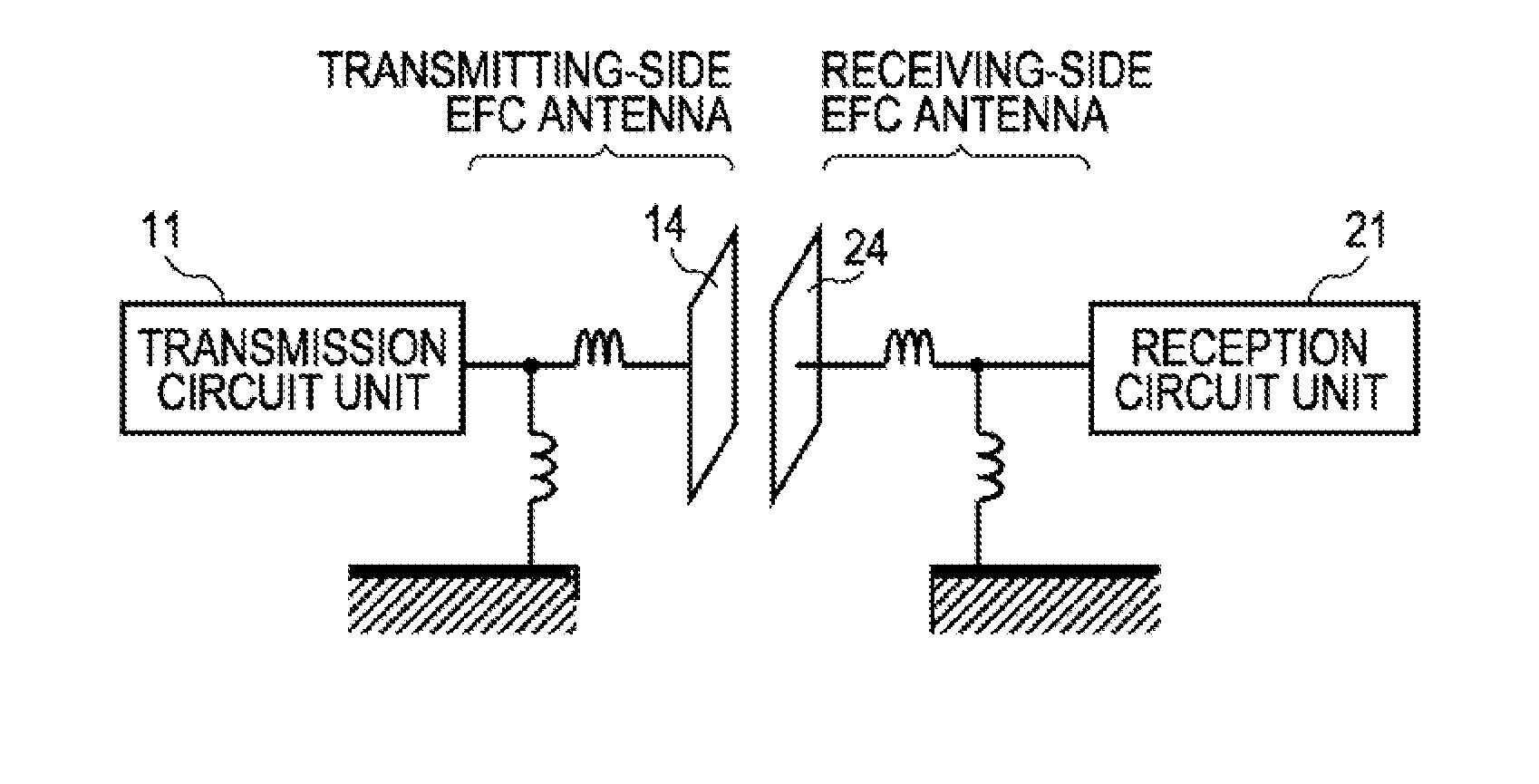
[0078]The present invention relates to a communication system for performing data transmission between information devices using an electrostatic field or an induced electric field.

[0079]According to a communication scheme based on an electrostatic field or an induced electric field, no radio waves are emitted in the absence of communication partners nearby since no coupling relationship occurs, and hence other communication systems are not disturbed. Even in the case where radio waves arrive from far away, an EFC antenna receives no radio waves, and hence the communication system is not interfered with by other communication systems.

[0080]In known radio communication using antennas, the strength of a radiated electric field is inversely proportional to the distance. In contrast, the strength of an induced electric field is attenuated in inverse proportion...


PUM


Abstract

A communication system includes the following elements: a transmitter including a transmission circuit unit configured to generate an RF signal for transmitting data and an EFC antenna configured to transmit the RF signal as an electrostatic field or an induced electric field; a receiver including an EFC antenna and a reception circuit unit configured to receive and process the RF signal received by the EFC antenna; and an impedance snatching unit configured to make an impedance of the EFC antenna of the transmitter equal to an impedance of the EFC antenna of the receiver. The RF signal is transmitted by electric-field coupling between the EFC antennas, facing each other, of the transmitter and the receiver.

Description

CROSS REFERENCES TO RELATED APPLICATIONS[0001]The present, invention contains subject matter related to Japanese Patent Application JP 2006-245614 filed in the Japanese Patent Office on Sep. 11, 2006, and Japanese Patent Application JP 2007-150500 filed in the Japanese Patent Office on Jun. 6, 2007, the entire contents of which are incorporated herein by reference.BACKGROUND OF THE INVENTION[0002]1. Field of the Invention[0003]The present invention relates to communication systems for communicating a large amount of data between information devices, and more particularly to a communication system for performing high-capacity data communication between information devices using an ultra-wideband (UWB) communication scheme using a radio-frequency (RF), wideband signal.[0004]More specifically, the present invention relates to a communication system, a communication apparatus, and an electric-field-coupling antenna (hereinafter called “EFC antenna”) for transmitting a UWB communication ...

Claims


Application Information

Patent Timeline
IPC IPC(8): H04B5/00H04B5/02
CPCH04B1/71635H04B5/02H04B5/0031H04B1/71637H04B7/24
Inventor WASHIRO, TAKANORI
Owner SONY CORP
Why Eureka
Try Eureka