Brake force detecting device

Inactive Publication Date: 2008-03-27
PANASONIC CORP +1
View PDF4 Cites 20 Cited by
  • Summary
  • Abstract
  • Description
  • Claims
  • Application Information

AI Technical Summary

Benefits of technology

[0007]It is therefore an object of the present invention to provide a brake force detecting device which can suppress the i

Problems solved by technology

Further, the strain in the sensor plate is generated only when the brake load

Method used


Image

  • Brake force detecting device
  • Brake force detecting device
  • Brake force detecting device

Examples


Embodiment Construction

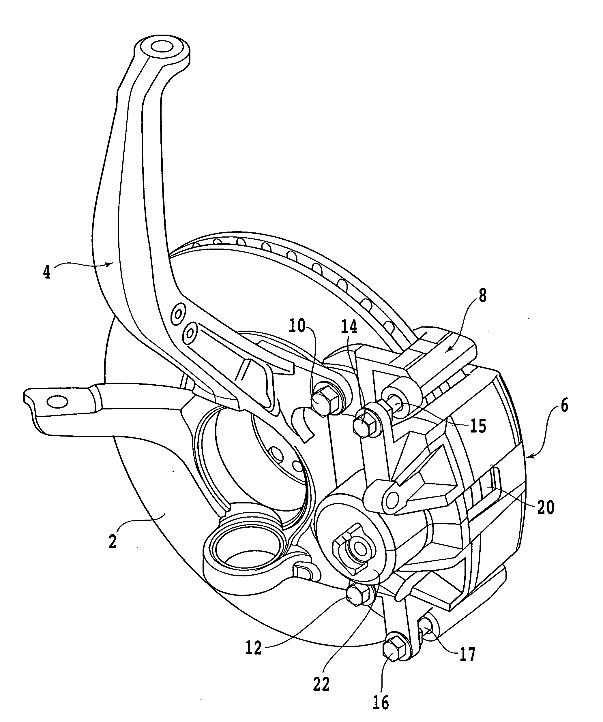
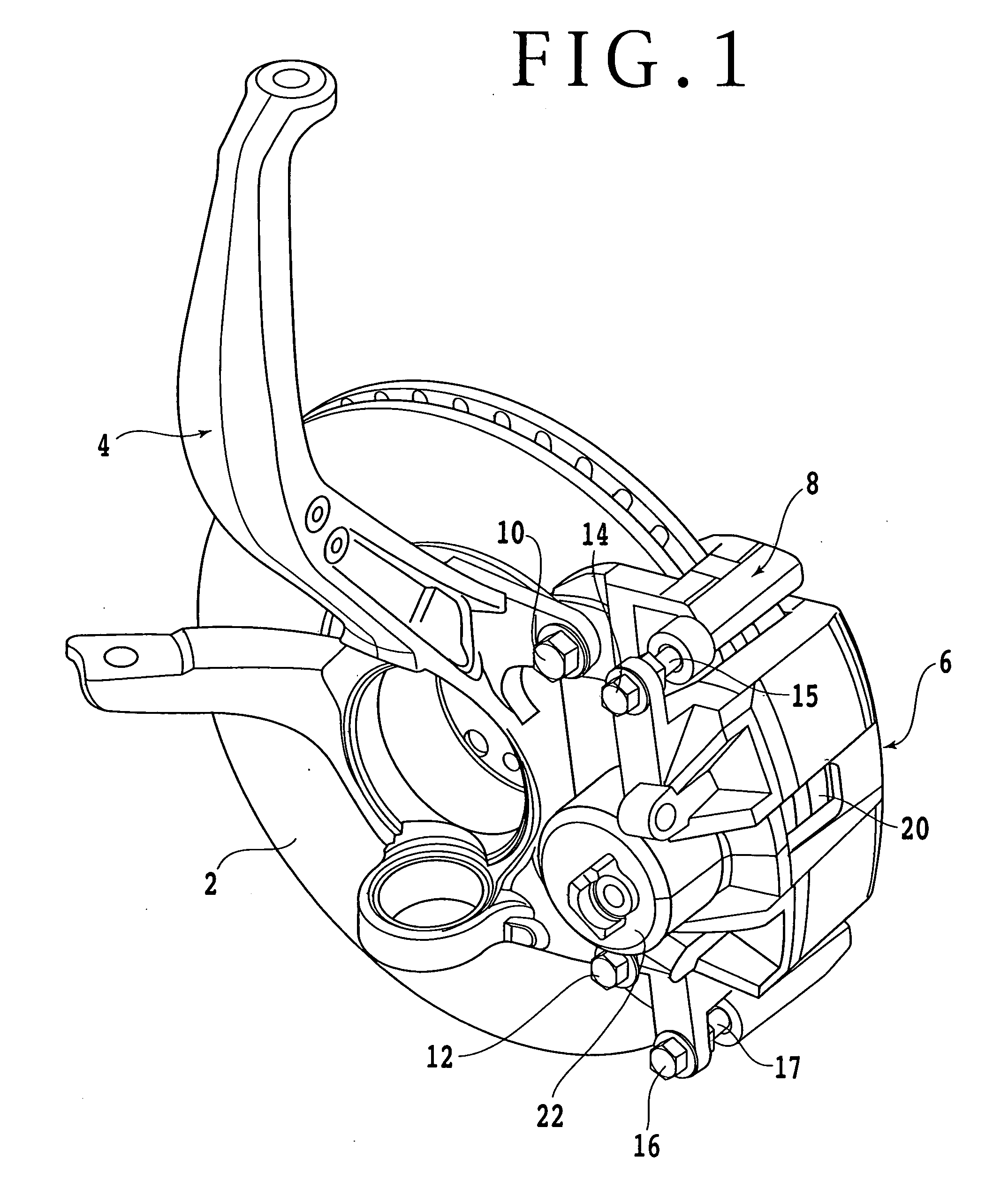
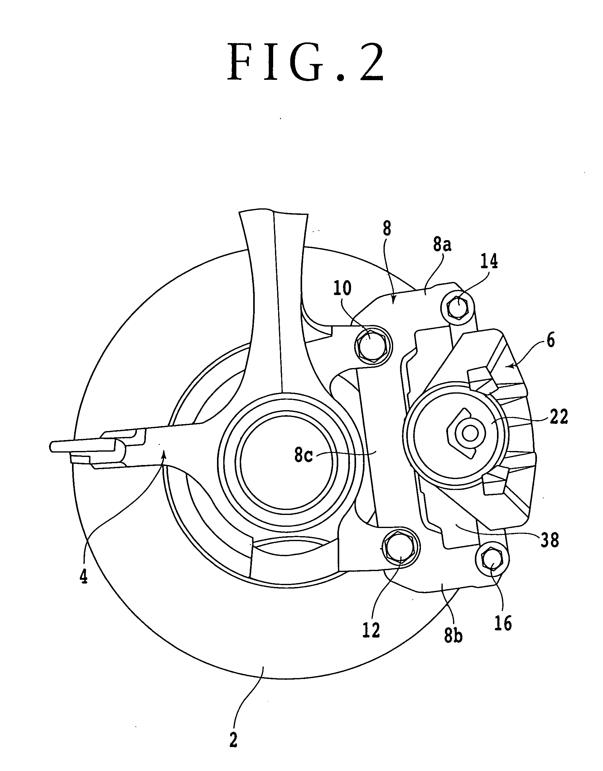
[0027]Some preferred embodiments of the present invention will now be described in detail with reference to the drawings. FIG. 1 is a perspective view of a disc brake including a brake force detecting device according to a first preferred embodiment of the present invention. FIG. 2 is a left side view of the disc brake shown in FIG. 1. As shown in FIGS. 1 and 2, a brake disc (disc rotor) 2 is fixed to a wheel (not shown), so that the brake disc 2 is rotated with the wheel. Reference numeral 4 denotes a knuckle (wheel support) for rotatably supporting the wheel. The knuckle 4 is connected through a suspension (not shown) to a vehicle body (not shown).

[0028]Reference numeral 8 denotes a caliper bracket, which is mounted to the knuckle 4 by two bolts 10 and 12. The caliper bracket 8 supports a pair of friction pads 19 and 21 at two opposite positions in the rotational direction (circumferential direction) of the brake disc 2, i.e., at a disc inlet position and a disc outlet position in...


PUM


Abstract

A brake force detecting device for detecting strain in a caliper bracket. The brake force detecting device includes a sensor plate fixed to the outside surface of a brake load receiving portion of the caliper bracket in the circumferential direction of a brake disc and a strain gauge attached to the sensor plate for detecting strain generated in the sensor plate. The strain gauge is connected to an amplifier.

Description

BACKGROUND OF THE INVENTION[0001]1. Field of the Invention[0002]The present invention relates to a brake force detecting device for detecting a brake force produced by a disc brake.[0003]2. Description of the Related Art[0004]In the case of performing braking control for a vehicle, a brake force is one of the important items of information. For example, if a brake force actually applied during braking can be detected, the condition of a road surface can be easily estimated. If the condition of a road surface can be estimated, ABS control (antiskid brake system control) can be performed more precisely, and the vehicle can therefore be braked to a halt safely in a short distance. Further, if a brake force applied to each wheel can be detected in braking during turning of the vehicle or during running on a slippery road surface having a low coefficient of friction (μ), the brake forces for all the wheels can be individually controlled to thereby allow safer running control of the vehic...

Claims


Application Information

Patent Timeline
IPC IPC(8): G06F17/00
CPCB60T8/52B60W2510/18F16D65/092F16D2066/005F16D66/00F16D2055/0008F16D65/095
Inventor HORIUCHI, TAKEHIROINAGAKI, HIROMIOHMORI, TAKAYUKIYOSHIUCHI, SHIGEHIROICHINOMIYA, NORITAKA
Owner PANASONIC CORP
Why Eureka
Try Eureka