Motorized airgun

a motorized air gun and air gun body technology, applied in the field of motorized air guns, can solve the problems of difficult shooting accuracy, difficult assembly, bulky airguns, etc., and achieve the effect of wide design range and simplified construction

Inactive Publication Date: 2008-04-03
VINBO INDAL
View PDF23 Cites 22 Cited by
  • Summary
  • Abstract
  • Description
  • Claims
  • Application Information

AI Technical Summary

Benefits of technology

[0005]The present invention is directed to motorized airguns, and especially to motorized toy airguns. Most preferably, the barrel and the pneumatic mechanism in such guns are disposed in a non-coaxial and angled relation to each other to provide for simplified construction and allow for a wide design range. In preferred aspects, at least part of the pneumatic mechanism is disposed in the handle of the gun and an intermediate conduit delivers the air blast from the pneumatic mechanism to the barrel.

Problems solved by technology

However, and especially where such motorized airguns have relatively high muzzle velocities, several problems are encountered.
For example, the compression chamber volume is often relatively large, thereby rendering the airgun bulky.
Moreover, due to relatively strong springs and other associated parts, assembly is often complex and requires a plurality of hardened materials to withstand the strong forces and impact of components.
Worse yet, as the compression springs in known motorized airguns are coaxially disposed relative to the barrel, recoil from unwinding of the spring and the impact of the plunger to its endpoint of movement makes accurate shooting difficult.
Still further, due to the relatively bulky dimensions of coaxial compression chambers, handgun design is typically limited to relatively bulky gun bodies.
Therefore, while there are numerous motorized airguns known in the art, all or almost all of them suffer from one or more disadvantages.

Method used


Image

  • Motorized airgun
  • Motorized airgun
  • Motorized airgun

Examples


Embodiment Construction

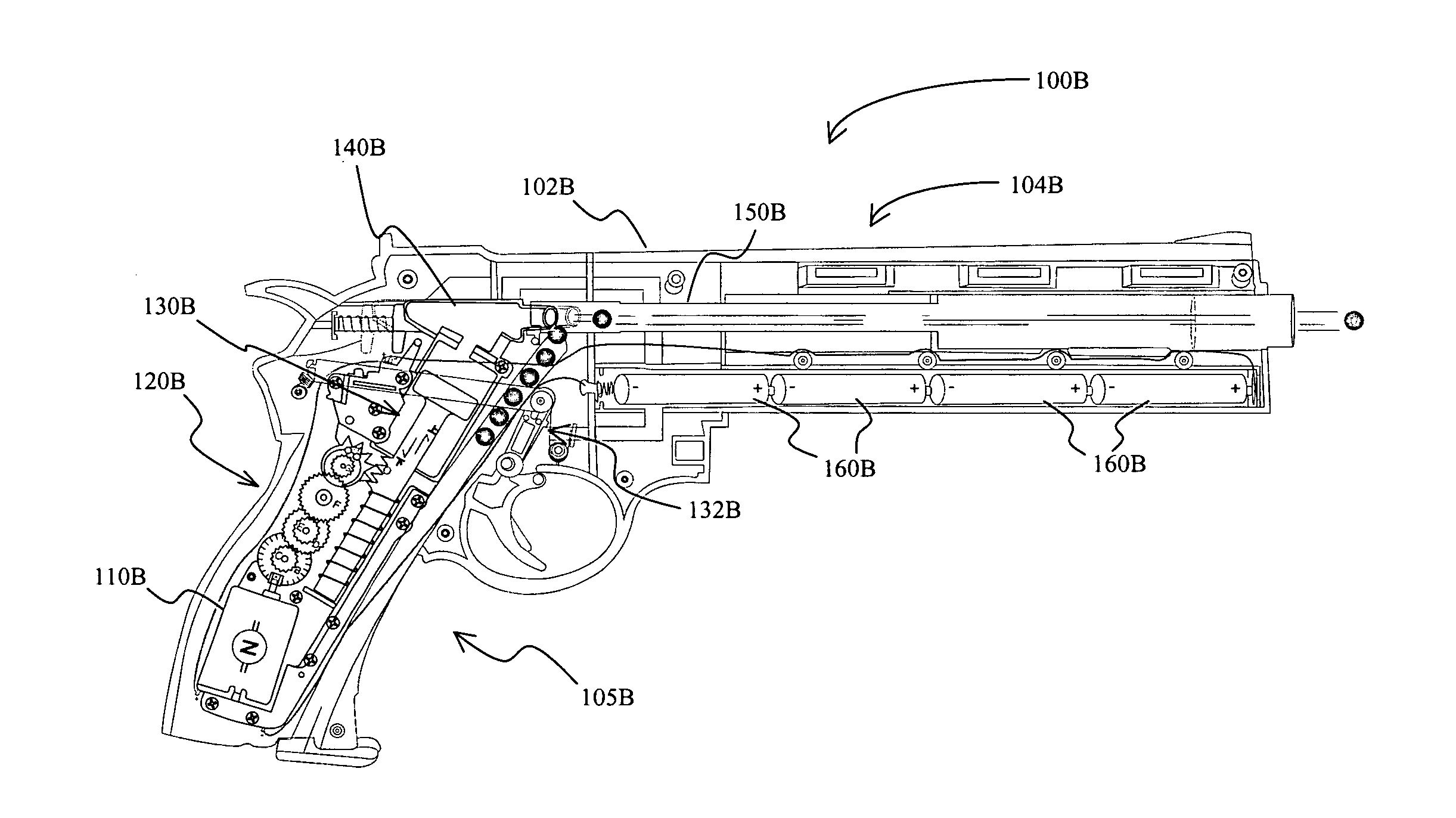
[0014]The inventor has discovered that a motorized airgun can be manufactured in a simple and effective manner that substantially improve performance and assembly while reducing cost. Most advantageously, the airguns contemplated herein comprise a barrel and a pneumatic cylinder that are in a non-coaxial and angled position relative to each other, wherein fluid coupling is achieved by an intermediate conduit. Such configuration not only allow spatial separation of the barrel from the pneumatic cylinder, but also eliminate recoil effects otherwise observed with airguns in which the springs and plunger are coaxially oriented relative to the barrel and trajectory of the projectile.

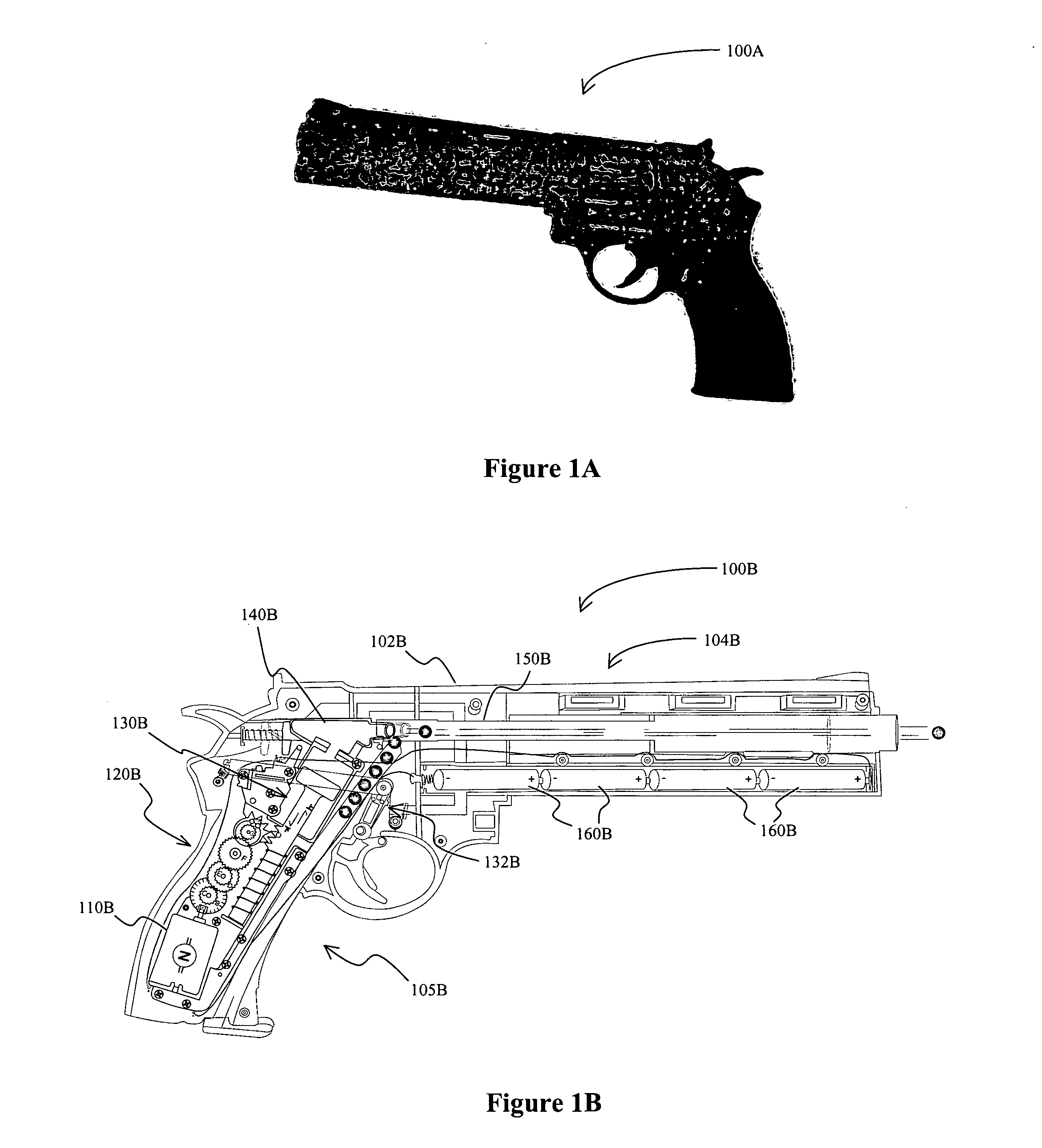
[0015]One exemplary motorized airgun is depicted in FIG. 1A in which the airgun 100A is configured as a revolver. FIG. 1B schematically illustrates the airgun of FIG. 1A in a opened configuration. Here, airgun 100B has a plastic housing 102B with a barrel portion 104B and a handle portion 105B. Within the han...


PUM


Abstract

An airgun has a pneumatic mechanism that is driven by an electrical motor to provide a blast of air, wherein the pneumatic mechanism is in a non-coaxial and angled position relative to the barrel, and wherein the air is delivered to the barrel via a preferably angled intermediate conduit. Spatial separation of the pneumatic mechanism from the axis of the barrel allows for substantially simplified constructions and use of light-weight material, and further provides a wide variety of handgun designs as the only space requirement for the projectile delivery portion is the barrel. Therefore, in one especially preferred aspect of the inventive subject matter, the airgun is configured a revolver.

Description

FIELD OF THE INVENTION[0001]The field of the invention is motorized air guns, and especially motorized toy air guns.BACKGROUND OF THE INVENTION[0002]Numerous airguns and toy airguns are known in the art, and most of such guns employ a reservoir of pre-compressed air or a manually tensioned spring mechanism to provide the motive force for the projectile. More recently, electric motors were implemented to provide at least some of the motive force, and typical examples for such motorized airguns are found in U.S. Pat. No. 4,899,717, U.S. Pat. No. 5,261,384, U.S. Pat. No. 6,564,788, JP6-235597, and JP2002-168594. However, and especially where such motorized airguns have relatively high muzzle velocities, several problems are encountered.[0003]For example, the compression chamber volume is often relatively large, thereby rendering the airgun bulky. Moreover, due to relatively strong springs and other associated parts, assembly is often complex and requires a plurality of hardened materia...

Claims


Application Information

Patent Timeline
Patent Type & Authority Applications(United States)
IPC IPC(8): F41B11/00
CPCF41B11/681F41B11/64
Inventor YEUNG, WAI KA
Owner VINBO INDAL
Why Eureka
Try Eureka