Torque limiter-incorporating one-way clutch

Inactive Publication Date: 2008-04-03
JTEKT CORP
View PDF4 Cites 39 Cited by
  • Summary
  • Abstract
  • Description
  • Claims
  • Application Information

AI Technical Summary

Benefits of technology

[0054]In the one-way clutch of the invention, the thickness of the outer ring is preferably not more than 90% of the thickness of the inner ring, and more preferably not more than 70%. In the one-way clutch, thus, the thickness of the outer ring is preferably not more than 90% of the thickness of the inner ring, and more preferably not more than 70%, and therefore the outer ring can be elastically deformed more easily than the inner ring, and by controlling the thickness of the outer ring, the precision of the torque limiter-operating torque can be easily enhanced.
[0055]According to a further aspect of the invention, there is provided a one-way clutch unit including an inner ring, an outer ring, engagement rollers, cam surfaces, and lock cancellation recesss; characterized in that a support bearing is integral with the one-way clutch, and a low-rigidity portion is formed at at least one of the inner ring and the outer ring at a boundary between the support bearing and the one-way clutch. A one-way clutch unit is required to have a support bearing for positioning (aligning) inner and outer rings, and without the support bearing, a wedge angle of the one-way clutch is changed, and a torque limiter-operating torque in the one-way clutch is varied. Therefore, there are conventional one-way clutch units in which a support bearing is integral with a one-way clutch. However, in such a one-way clutch unit, the rigidity of the one-way clutch is influenced by the rigidity of the support bearing, and in order that adverse effects of the rigidity of the support bearing will not be exerted on the one-way clutch, the support bearing need to be mounted sufficiently apart from the one-way clutch. Alternatively, a low-rigidity portion is provided in order that adverse effects of the rigidity of the support bearing will not be exerted on the one-way clutch. In the one-way clutch unit of the invention, the low-rigidity portion is formed at at least one of the inner ring and the outer ring at the boundary between the support bearing and the one-way clutch, and therefore adverse effects of the rigidity of the support bearing on the one-way clutch are eliminated. However, even the low-rigidity portion must have necessary strength and rigidity for the transmission of a torque.
[0056]In the one-way clutch unit of the invention, preferably, the low-rigidity portion is provided at the outer ring. Generally, in a torque limiter-incorporating one-

Problems solved by technology

When this rotation variation increases, a variation in tension of the belt increases, and there is a fear that this tension variation of the belt can not be absorbed, and slip may develop between contact portions of the pulley and belt, so that the belt may be worn or damaged.
Therefore, when an overload is applied, there is encountered a problem that the belt slips relative to the pulley, so that the belt is subjected to seizure and damage.
Namely, when the torque limiter is operated, a clearance develops between each roller and a corresponding spring (urging member) urging it, and the springs are not retained by any part, and therefore the springs become free, and this leads to a possibility that the springs are bitingly held between an outer ring and an inner ring.
Namely, when the rollers are to be fitted into the respective recesses, slip (engagement slip) occurs because of a reduced friction coefficient, and this leads to a possibility that the one-way clutch is damaged or broken by popping.
However, it is necessary to additionally form the recesses in the cam surfa

Method used


Image

  • Torque limiter-incorporating one-way clutch
  • Torque limiter-incorporating one-way clutch
  • Torque limiter-incorporating one-way clutch

Examples


first embodiment

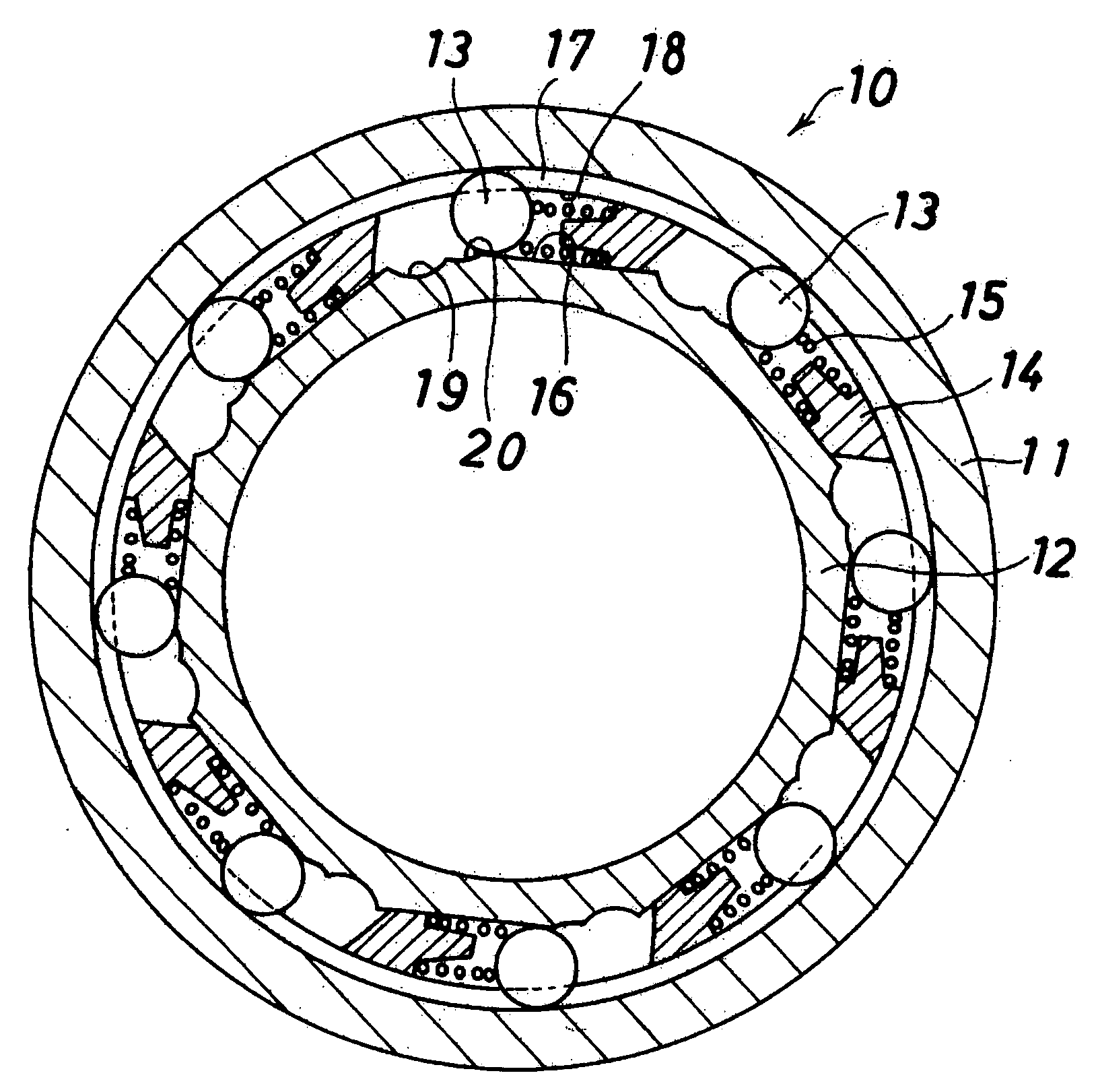
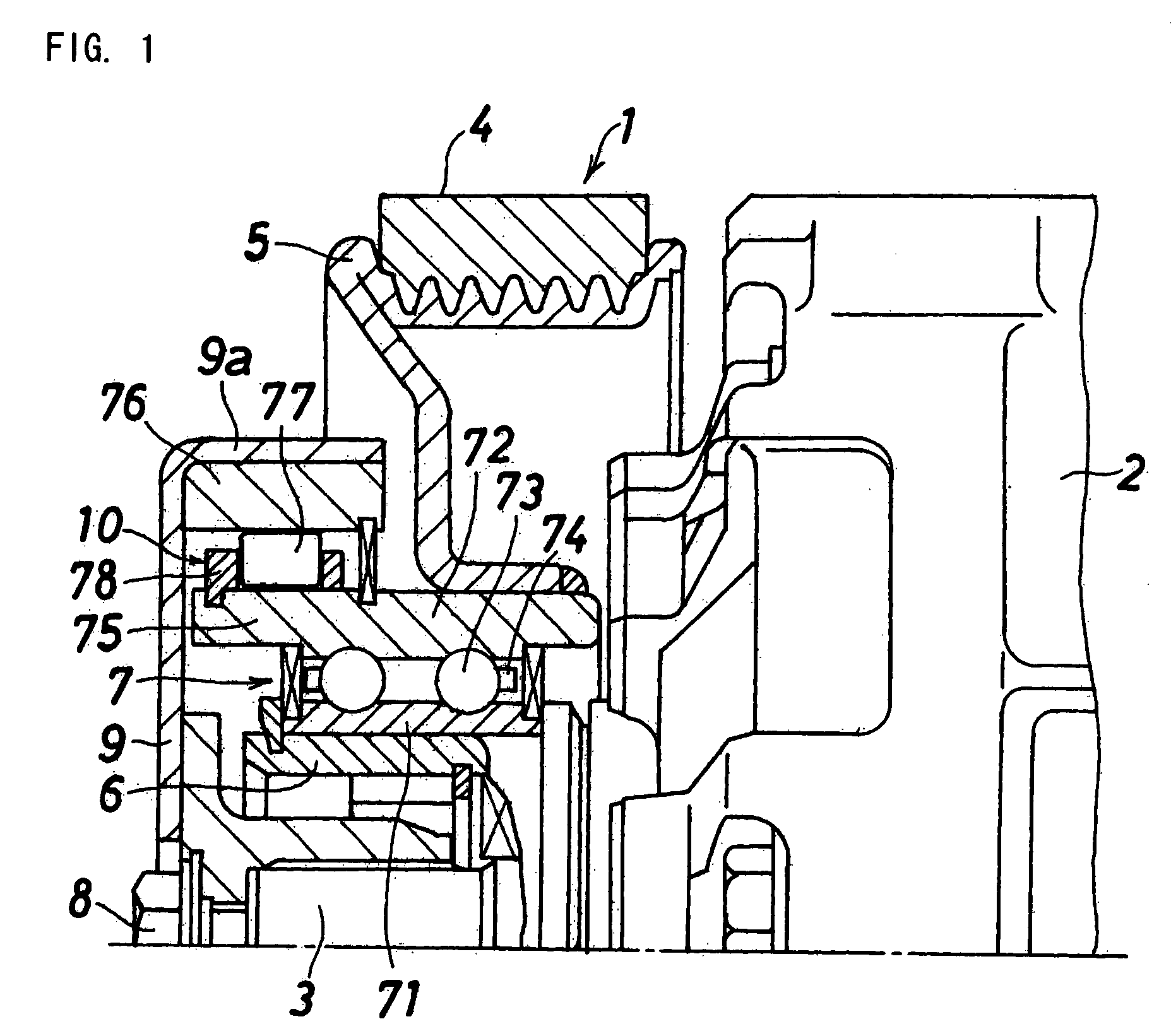
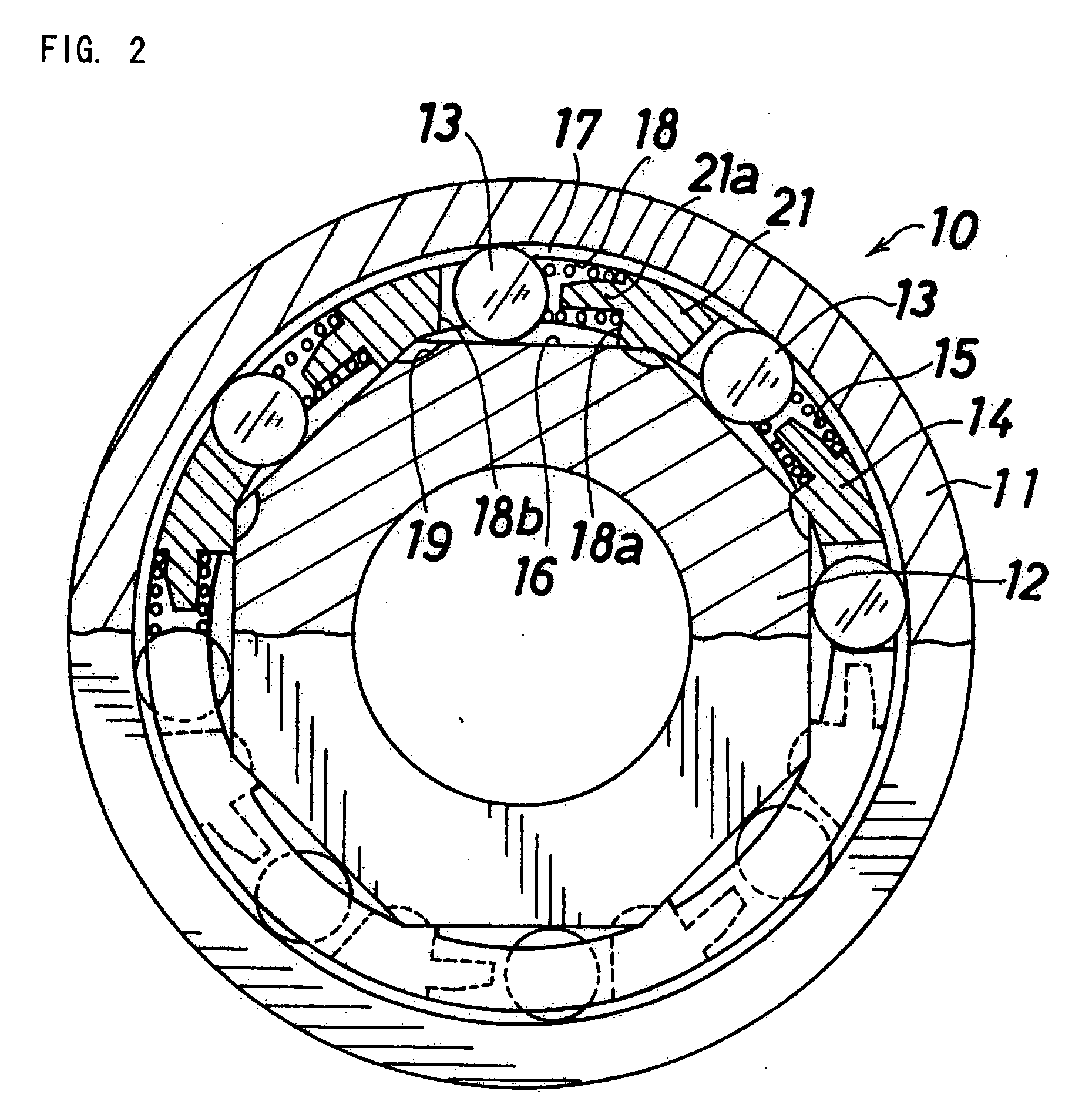
[0076]FIGS. 2 and 3 show one preferred embodiment of a torque limiter-incorporating one-way clutch of the present invention.

[0077]This one-way clutch 10 is used as the one-way clutch 10 shown in FIG. 1, and comprises a cylindrical outer ring 11, an inner ring 12 having an outer peripheral surface of a polygonal shape having cam surfaces 16 each defining a locking position and a free position, a plurality of rollers 13 (serving as biting members) which are disposed respectively in wedge-like spaces 17 each formed between the corresponding cam surface 16 and an inner peripheral surface of the outer ring 11, and are bitingly held between the outer ring 11 and the inner ring 12 upon rotation of the outer and inner rings 11 and 12 relative to each other in one direction (locking direction), and are brought out of biting engagement with the outer and inner rings 11 and 12 upon relative rotation in the other direction (free direction), coil springs (urging members) 15 respectively urging t...

second embodiment

[0090]FIGS. 4 to 6 show a second embodiment of a torque limiter-incorporating one-way clutch of the invention.

[0091]As shown in FIG. 4, the one-way clutch 10 comprises a cylindrical outer ring 11, an inner ring 12 having an outer peripheral surface of a polygonal shape having cam surfaces 16 each defining a locking position and a free position, a plurality of rollers 13 (serving as biting members) which are disposed respectively in wedge-like spaces 17 each formed between the corresponding cam surface 16 and an inner peripheral surface of the outer ring 11, and are bitingly held between the outer ring 11 and the inner ring 12 upon rotation of the outer and inner rings 11 and 12 relative to each other in one direction (locking direction), and are brought out of biting engagement with the outer and inner rings 11 and 12 upon relative rotation in the other direction (free direction), coil springs (urging members) 15 respectively urging the rollers 13 in the biting direction (toward nar...

third embodiment

[0108]FIGS. 7 and 8A show a third embodiment of a torque limiter-incorporating one-way clutch of the invention.

[0109]This one-way clutch 10 is used as the one-way clutch 10 shown in FIG. 1, and comprises a cylindrical outer ring 11, an inner ring 12 having an outer peripheral surface of a polygonal shape having cam surfaces 16 each defining a locking position and a free position, a plurality of rollers 13 (serving as biting members) which are disposed respectively in wedge-like spaces 17 each formed between the corresponding cam surface 16 and an inner peripheral surface of the outer ring 11, and are bitingly held between the outer ring 11 and the inner ring 12 upon rotation of the outer and inner rings 11 and 12 relative to each other in one direction (locking direction), and are brought out of biting engagement with the outer and inner rings 11 and 12 upon relative rotation in the other direction (free direction), coil springs (urging members) 15 respectively urging the rollers 13...


PUM


Abstract

A length of each pocket of a cage in a circumferential direction is smaller than the sum of an outer diameter of a roller and a free length of a coil spring. The cage can rotate relative to an inner ring having cam surfaces in accordance with revolution of the rollers in an overload-applied condition, and the cage can not rotate in a direction opposite to a direction of revolution of the rollers in the overload-applied condition.

Description

BACKGROUND OF THE INVENTION[0001]This invention relates to a one-way clutch, and more particularly to a torque limiter-incorporating one-way clutch in which when the clutch is subjected to an overload in a locked state, the locked state is canceled.[0002]One-way clutch is provided, for example, in a pulley unit of an engine auxiliary equipment driven by a crank shaft of an automobile engine through a belt. Examples of such engine auxiliary equipments include a compressor for an air conditioner, an alternator, a water pump and a cooling fan.[0003]For example, there are various compressors for an automobile air conditioner, and in any of these compressors, rotating power of a crank shaft of an automobile engine is used as a drive source. The transmission of power from the crank shaft to a rotation shaft of the compressor is effected through a belt.[0004]The rotation of the crank shaft varies according to a combustion cycle of the engine, and therefore a variation in rotation is transm...

Claims


Application Information

Patent Timeline
IPC IPC(8): F16D41/06
CPCF16D41/067F16D41/064F16D2041/0608
Inventor WATANABE, HAJIMEFUJIWARA, HIDEKIYAMATANI, TOMOYAMAEDA, MASAKI
Owner JTEKT CORP
Why Eureka
Try Eureka