Bearing isolator and conveyor roller

a technology of bearing isolator and conveyor roller, which is applied in the direction of conveyor parts, mechanical equipment, transportation and packaging, etc., can solve the problems of system shutdown, affecting so as to reduce the energy consumption and increase the reliability of the bearing

Inactive Publication Date: 2008-04-03
WAUKESHA ACQUISITION
View PDF17 Cites 24 Cited by
  • Summary
  • Abstract
  • Description
  • Claims
  • Application Information

AI Technical Summary

Benefits of technology

[0011] It is an objective of the present art to claim and disclose an improvement on the prior art and present viable solutions to the disadvantages of the prior art, including increased reliability of and reduction of energy consumed by roller assemblies and conveyor systems of the prior art.
[0012] It is a further objective of the present art to claim and disclose a method of monitoring the improved bearing isolator in all its embodiments. In this method, the improved bearing isolator may be used as an indicator in connection with a detector system that collects operational data useful in operating the equipment associated with the improved bearing isolator and cooperatively engaged with the improved bearing isolator. The disclosed method may also be used for predictive and preventative maintenance of the improved bearing isolator and any equipment associated or systematically engaged therewith.
[0013] One embodiment of the present invention as illustrated in FIGS. 3, 4A-4C, 6, and 7 is a non-contacting, non-wearing, and non-energy consumptive sealing system that provides adequate protection for primary bearings as may be found in the prior art and particularly those primary bearings used in combination with conveyor roller bearings as found in the prior art. In a first embodiment of the present invention, the bearing seals of the conveyor rollers of the prior art may be replaced with the present art. In this first embodiment, the improved bearing isolator is a substitute for lube containment shields, and the improved bearing isolator will not wear or degrade in use. Since the roller housing rotates around a stationary shaft, high quality and long lasting grease lubricant centrifugates (i.e., migrates through and by centrifugal acceleration) during rotation to the inner track of the outer race of the primary bearing and interacts with the rolling components of the primary bearings. In the embodiments disclosed, at all times there will be no frictional engagement with the sealing components or the improved bearing isolator assemblies.

Problems solved by technology

Any one of the seals or bearings could severely degrade and cause the system to shut down.
A stalled roller may put undue strain on the belt being used for holding the product, and when a bearing grinds to a halt, the resulting heat produced from the increased friction may initiate combustion of various combustible materials in and around the bearing location.
As soon as wear occurs, sealing efficiency degrades so as to be completely ineffective.
Reliability of the system suffers because of the very large number (as calculated above) of wearing and vulnerable components.
The prior art contacting seals are prone to wear and are energy consumptive because of the frictional drag inherent in their design.
Typical environmentally difficult applications are mines, cement works, coal-fired electric utilities and dock installations, among others.
As found by applicant, the prior art fails to achieve the objective.
Given the large numbers of conveyor rollers typically installed and used, it is difficult for operators to be alerted to a primary bearing failure until a secondary event occurs.
Many times, this secondary event is initiation of a smoldering fire or smoke from conveyed materials deposited in close proximity to the conveyor due to the heat often generated from primary bearing failure.
This heat generation that may cause a smoldering fire typically occurs from ferrous metal to ferrous metal contact, as does sparking, both of which are allowed by primary bearing failure.
The typical bearing seal is hidden from external inspection / view and is made of plastic so that it does not only conduct heat poorly but is prone to fail upon rapid heating from either combustion or ferrous metal to ferrous metal contact.
As is well known to those practiced in the art, ferrous metal to ferrous metal contact (rubbing) may be severe enough to raise the metal temperatures to 2500 degrees Fahrenheit (1370 degrees Celsius) and result in partial or full melting of the primary bearing and the destruction thereof.

Method used


Image

  • Bearing isolator and conveyor roller
  • Bearing isolator and conveyor roller
  • Bearing isolator and conveyor roller

Examples


Embodiment Construction

Listing of Elements

[0046]

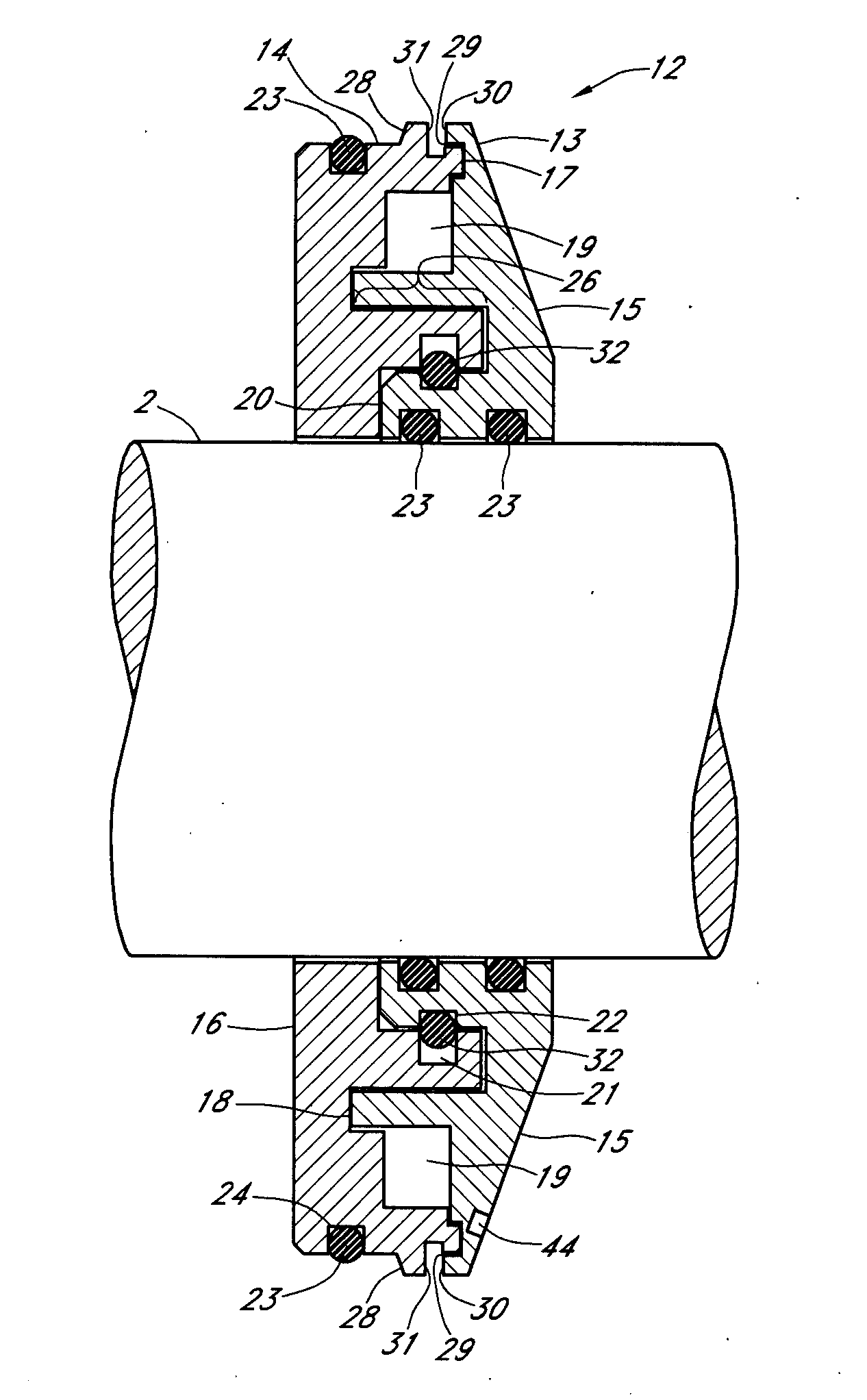
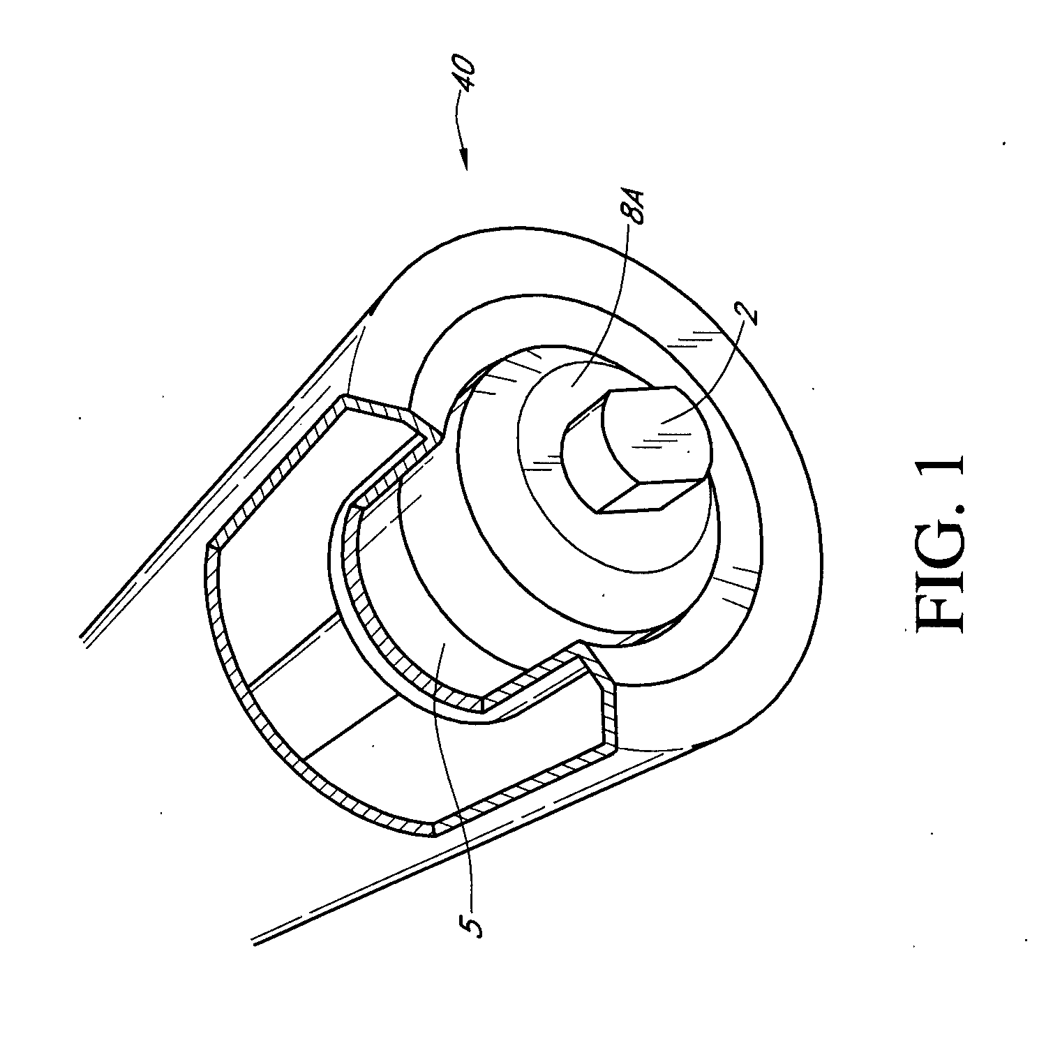
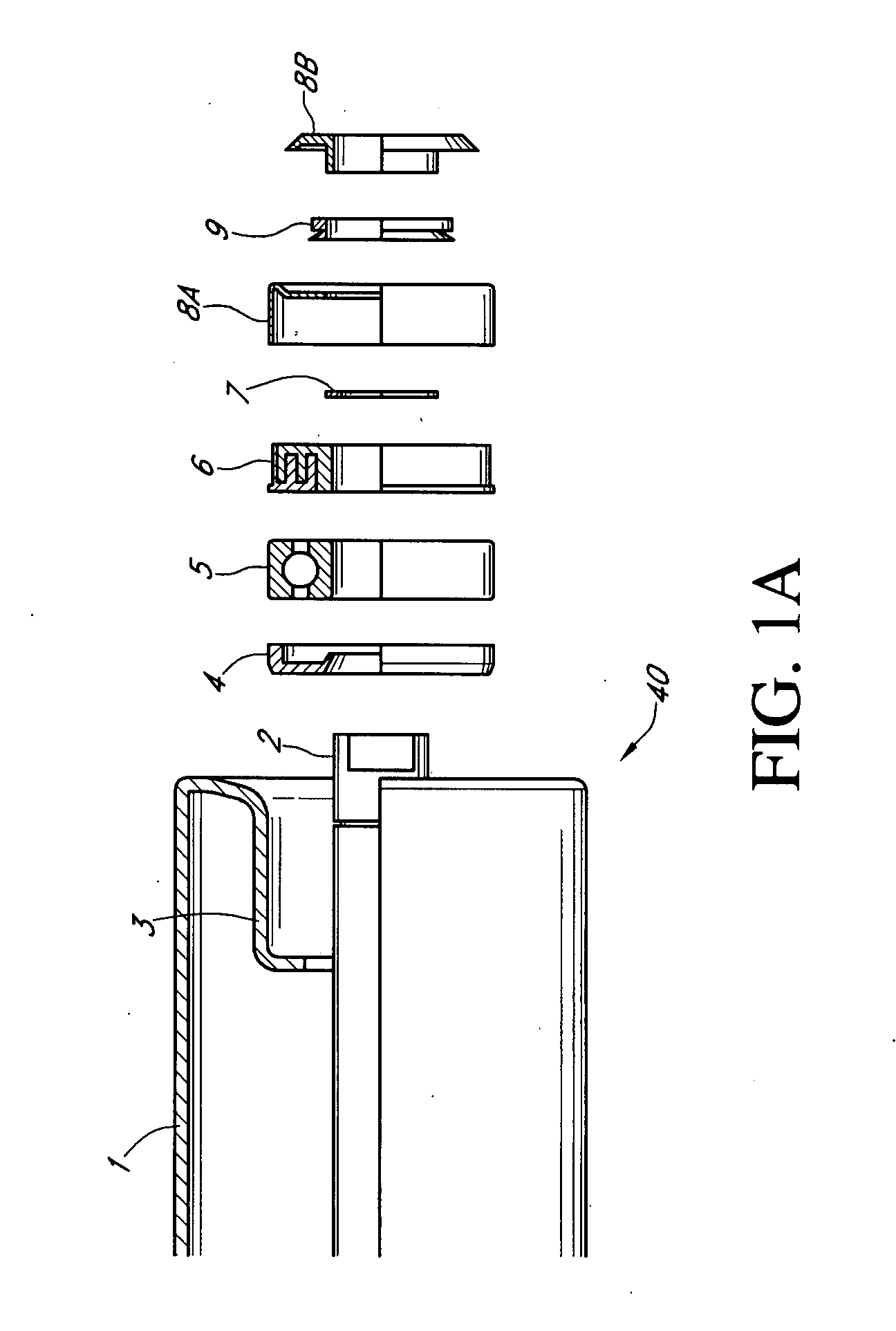
ELEMENT DESCRIPTIONELEMENT #Conveyor Roller Shell1Shaft2Bearing Housing3Inner Seal4Primary Bearing5Labyrinth Seal6Circlip7Cover8AStone Guard8BWeather Seal9Intentionally Blank10Intentionally Blank11Improved Bearing Isolator12Stator13Rotor14Stator Exterior End Face15Rotor Interior End Face16Exterior Interface Passage17Interior Interface Passage18Intermediate Annular Chamber19Immediate Interface Passage20Rotor Unitizing Ring Groove21Stator Unitizing Ring Groove22O-Ring23Rotor O-ring Groove24First Stator O-ring Groove25Axial Engagement Surface Area26Second Stator O-ring Groove27Ramped Shoulder28Axial Interface Passage29Inner Side of Stator30Inner Side of Rotor31Unitizing Ring32Intentionally Blank33Intentionally Blank34Inner Bearing Race35Outer Bearing Race36Intentionally Blank37Primary Bearing Shield38Primary Bearing Seal39Conveyor Roller40Polyurethane Structure41Thermal Scanner42IR Camera43Sensor Port44Grease Zerk45Grease Passage46First IR Line of Sight110Seco...


PUM


Abstract

A conveyor roller assembly and an improved bearing isolator are disclosed. The conveyor roller assembly comprises a fixed shaft, a conveyor roller mounted for rotation about said shaft, wherein said conveyor roller comprises, a conveyor roller shell, a bearing housing at either end, a primary bearing having an inner race secured to said shaft and an outer race secured to said bearing housing, a rotor sealingly secured to said conveyor roller, and a stator sealingly secured to said shaft, wherein said rotor and said stator cooperate to form a non-contacting exterior interface passage, a non-contacting intermediate annular chamber, a non-contacting interior interface passage, and a non-contacting immediate interface passage.

Description

CROSS REFERENCE TO RELATED APPLICATIONS [0001] Applicant claim priority under 35 U.S.C. § 119(e) of provisional U.S. Patent Application Ser. No. 60,842,718 filed on Sep. 7, 2006 which is incorporated by reference herein.FIELD OF INVENTION [0002] The present invention relates to both an improved bearing isolator which may be used alone or in combination with a conveyor roller type arrangement for improved contaminant exclusion in industrial applications and an improved monitoring method and system allowed by said apparatus. When the improved bearing isolator is used in combination with a conveyor roller, the exterior end face of the improved bearing isolator provides an indicator surface for monitoring. STATEMENT REGARDING FEDERALLY SPONSORED RESEARCH OR DEVELOPMENT [0003] No federal funds were used to develop or create the invention disclosed and described in the patent application. REFERENCE TO SEQUENCE LISTING, A TABLE, OR A COMPUTER PROGRAM LISTING COMPACT DISK APPENDIX [0004] No...

Claims


Application Information

Patent Timeline
Patent Type & Authority Applications(United States)
IPC IPC(8): B65G13/00F16C33/74
CPCB65G39/09B65G43/02F16C19/06F16C13/022F16C33/80F16C2326/58
Inventor ORLOWSKI, DAVID C.HOEHLE, NEIL F.
Owner WAUKESHA ACQUISITION
Why Eureka
Try Eureka