Lock detection circuit and method for phase locked loop system

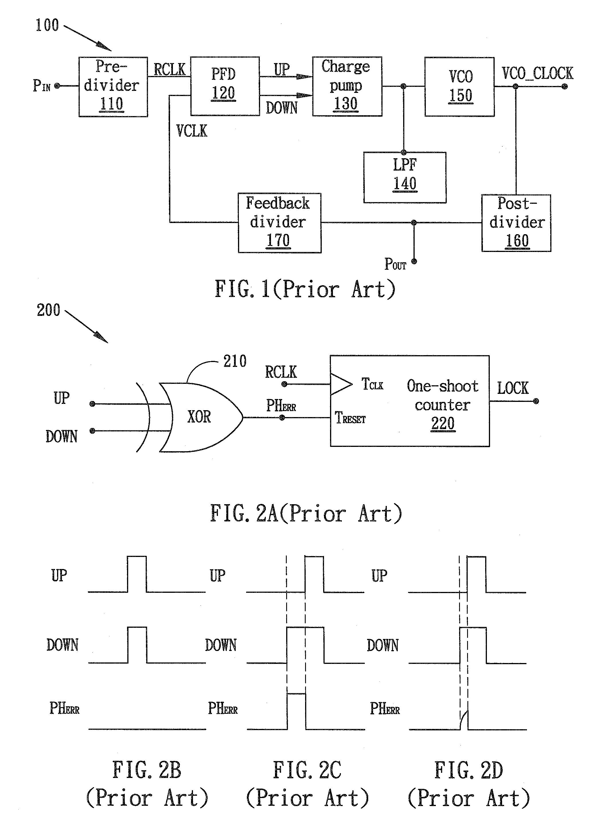
a phase locking loop and lock detection technology, applied in the direction of pulse transformers, pulse techniques, digital transmission, etc., can solve the problems that the phase error tolerance of the conventional lock detection circuit b>200/b> may not meet a practical requirement, and lack the capability and flexibility to adjust the phase error tolerance for different applications

Active Publication Date: 2008-04-03
VIA TECH INC
View PDF16 Cites 16 Cited by
  • Summary
  • Abstract
  • Description
  • Claims
  • Application Information

AI Technical Summary

Problems solved by technology

In other words, the phase error tolerance of the conventional lock detection circuit 200 may fail to meet a practical requirement.
It lacks the capability and flexibility to adjust the phase error tolerance for different applications.

Method used


Image

  • Lock detection circuit and method for phase locked loop system
  • Lock detection circuit and method for phase locked loop system
  • Lock detection circuit and method for phase locked loop system

Examples


Embodiment Construction

[0023]In this specification (as well as the claims), being logically asserted means being set to logic “1” which may refer to a high voltage level in a positive logic system or a low voltage level in a negative logic system. Similarly, for a logic signal, being asserted means being set to logic “1”.

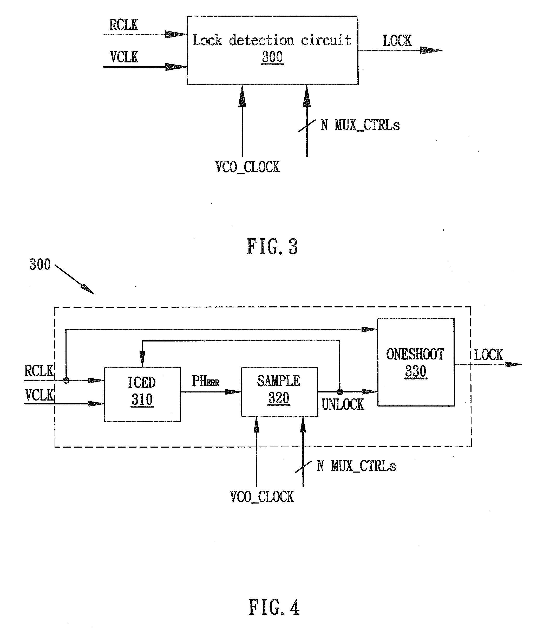
[0024]FIG. 3 shows a block diagram of a lock detection circuit 300 in accordance with an embodiment of the present invention. The lock detection circuit 300 may be connected to the typical phase locked loop system 100 as shown in FIG. 1, so as to determine whether the phase locked loop system 100 is already in locked state. Particularly, the lock detection circuit 300 receives the reference clock signal RCLK, the divided VCO clock signal VCLK, and the voltage controlled oscillator (VCO) clock VCO_CLOCK of the phase locked loop system 100 of FIG. 1. A VCO clock with frequency greater than that of the input clock signal PIN of the phase locked loop system 100 is feasible for embodiments of ...


PUM


Abstract

A lock detection circuit and method are disclosed for phase locked loop (PLL) systems. The lock detection circuit primarily includes a delay unit and an asserting logic unit. The delay unit receives the phase error signal of the PLL and produces a present phase error signal, and then accordingly generates at least one delayed phase error signal. The asserting logic unit generates an unlock indicating signal (UNLOCK) according to the present phase error signal and the delayed phase error signal. A phase lock indicating signal will be asserted if the unlock indicating signal is not asserted within a predetermined number of counting pulses.

Description

BACKGROUND OF THE INVENTION[0001]1. Field of the Invention[0002]The present invention relates to integrated circuit design, and more particularly to a lock detection circuit and method for a phase locked loop (PLL) system.[0003]2. Description of the Prior Art[0004]FIG.1 shows a block diagram of a typical phase locked loop system in accordance with prior art. The phase locked loop system 100 includes a pre-divider 110, a phase frequency detector (PFD) 120, a charge pump 130, a low pass filter (LPF) 140, a voltage controlled oscillator (VCO) 150, a post-divider 160, and a feedback divider 170. The pre-divider 110 receives an input clock signal PIN and outputs a divided reference clock signal RCLK to the phase frequency detector 120. The phase frequency detector 120 is connected to the feedback divider 170 and receives a divided VCO clock signal VCLK therefrom. The phase frequency detector 120 has two output terminals outputting an UP clock signal and a DOWN clock signal to the charge ...

Claims


Application Information

Patent Timeline
Patent Type & Authority Applications(United States)
IPC IPC(8): H03D3/24
CPCH03L7/095
Inventor HUANG, CHUN-CHE
Owner VIA TECH INC
Why Eureka
Try Eureka