
Electrosurgical generator and method for simulating output signals

a generator and output signal technology, applied in the field of electrosurgical generators, can solve the problems of reducing the amount of power reaching the tissue, changing the output characteristics of these sensors, and high current may create excess tissue damage, so as to achieve rapid and precise power regulation, the effect of reducing the lag time or phase lag of the control loop

Active Publication Date: 2008-04-03
CONMED CORP
View PDF6 Cites 33 Cited by
  • Summary
  • Abstract
  • Description
  • Claims
  • Application Information

AI Technical Summary

Benefits of technology

The present invention is about an electrosurgical generator that accurately and rapidly simulates the voltage and current values of an electrosurgical output signal using only the input current and voltage signals at the input winding of the transformer. This is achieved by one or more mathematical algorithms that compensate for the distortion of the transformer. The simulation circuit uses logic gates to logically combine the sensed signals and computes the simulated output signals quickly. The advantages of this invention include highly responsive feedback power control with minimal delay, enhanced monitoring of patient parameters, and improved control of the electrosurgical generator. The invention also includes a method of accurately simulating the voltage and current of an electrosurgical output signal using a transformer with distortion characteristics compensated for by a mathematical simulation algorithm.

Problems solved by technology

On the other hand, when the active electrode passes from high impedance tissue into low impedance tissue, high current is momentarily delivered into the low impedance tissue and that high current may create excess tissue damage.
However, the output sensors impose additional capacitive, resistive and / or inductive loads on the electrosurgical output signal, thereby changing its output characteristics.
The load from these sensors decreases the amount of power reaching the tissue and increases leakage current.
Leakage current can cause a lack of accuracy in output power regulation, or be a source of unintended patient burns and hazards to operating room personnel.
The output voltage sensors must have the capability of withstanding high output voltage, and therefore the sensors may be relatively costly.
However, these simple relationships are valid only for an ideal transformer, and an electrosurgical power output transformer is far from an ideal circuit element.
Consequently, the voltage and current signals from the primary winding voltage and current sensors do not accurately represent the voltage and current of the output signal from the secondary winding in a typical electrosurgical power output transformer.
Parasitic capacitances between the windings and the core of the output transformer store and divert different amounts of energy at different frequencies, and therefore cause changes in the spectral energy content or bandwidth of the output signal compared to the input signals.
Core losses consume energy from the primary signals, as do the resistances of the winding conductors.
Those approximations do not provide the precision desired for accurate control and monitoring of the electrosurgical output signal applied to the patient.
Even in those cases where the output signals are sensed by output sensors, the signals supplied by the output sensors may not be processed quickly enough to be effective in precisely controlling the output power from an electrosurgical generator.
A control loop time lag or phase lag, which is that time between acquiring the sensed signals and making an adjustment to the output signals, may be so long that a response cannot be achieved quickly enough to obtain or maintain the desired effect.

Method used


Image

  • Electrosurgical generator and method for simulating output signals
  • Electrosurgical generator and method for simulating output signals
  • Electrosurgical generator and method for simulating output signals

Examples


Embodiment Construction

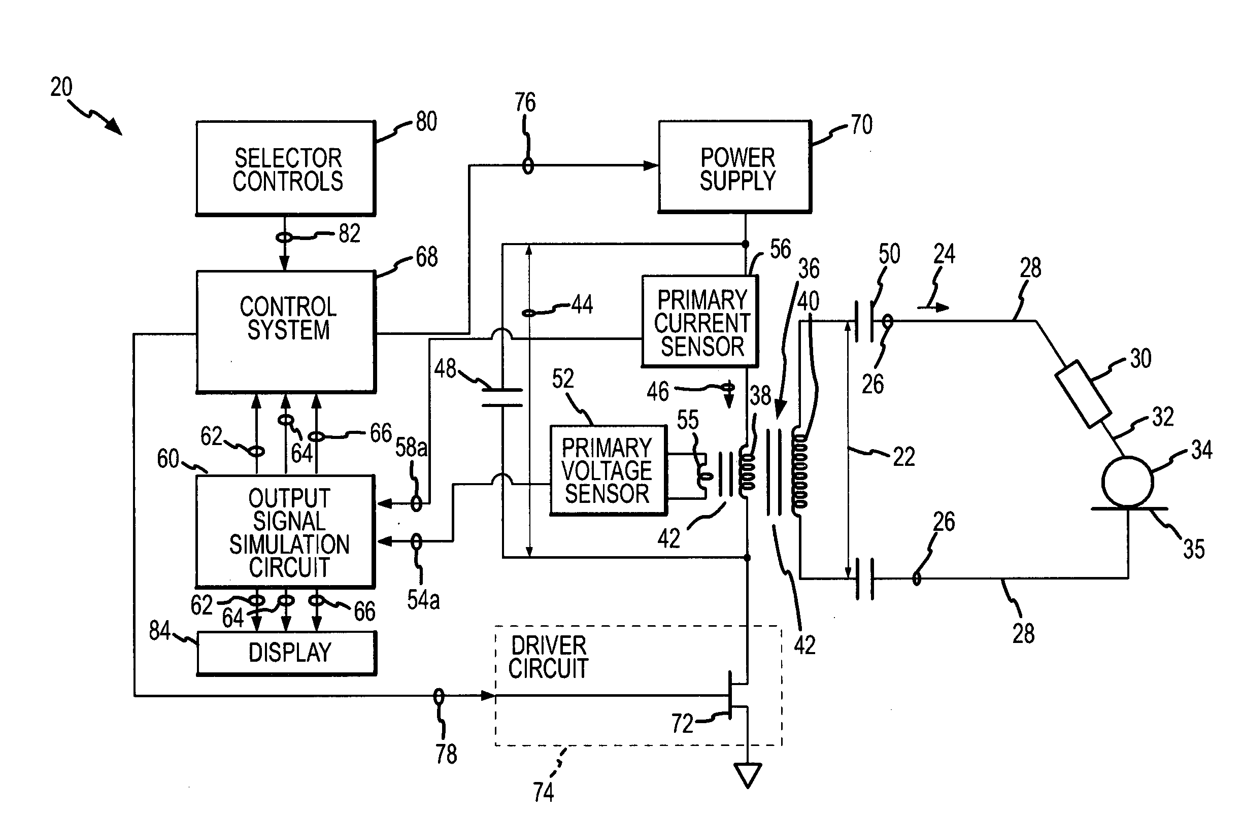
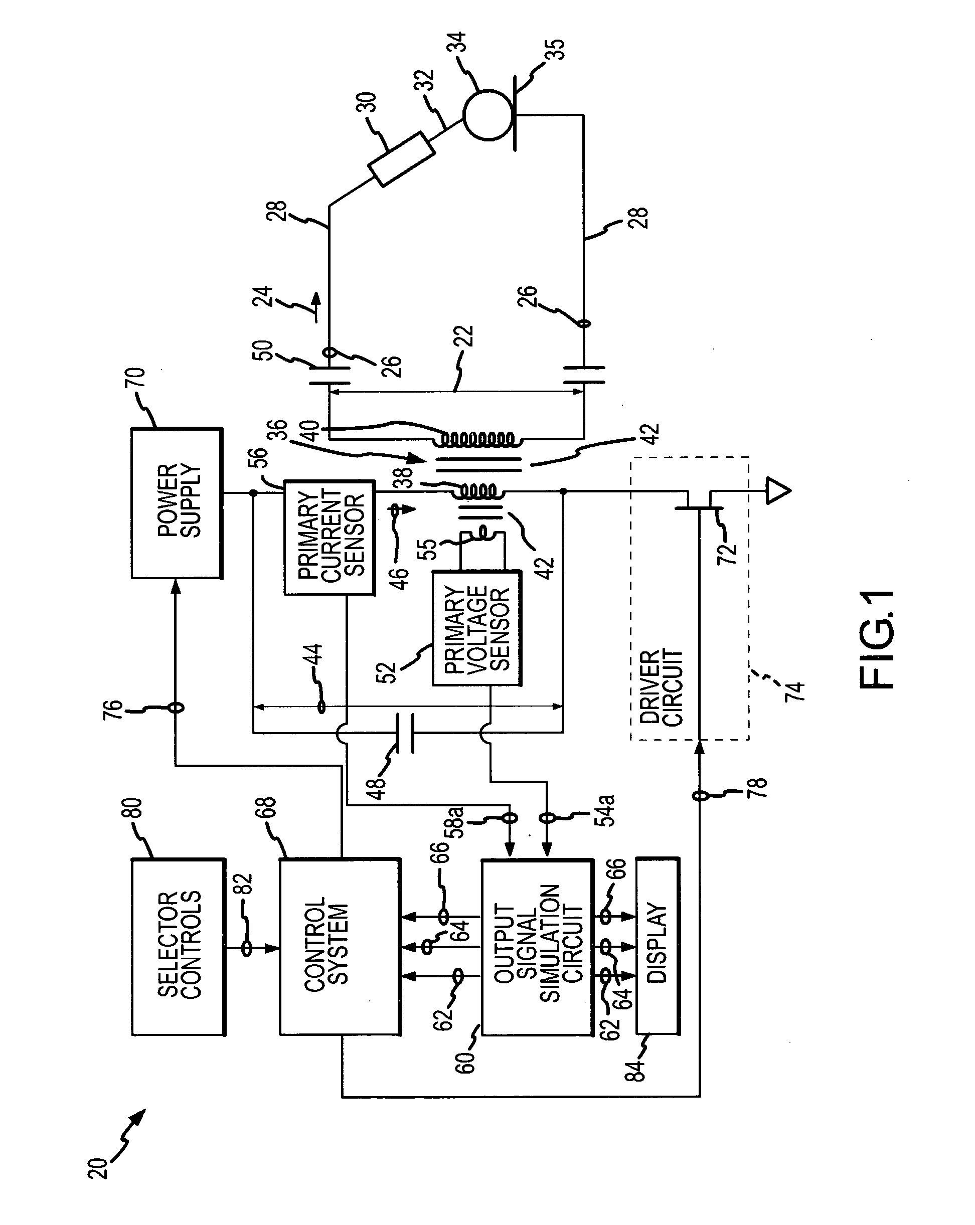
[0024]An electrosurgical generator 20 which incorporates the present invention is shown in FIG. 1. The electrosurgical generator 20 creates and delivers an electrosurgical output signal formed by an output voltage 22 and an output current 24. The electrosurgical output signal is delivered from output terminals 26 of the generator 20 and is conducted over a lead or conductor 28 to an applicator or handpiece 30. The handpiece 30 includes an active electrode 32 through which the output voltage 22 and output current 24 are applied at a surgical site to tissue of a patient 34 by the surgeon manipulating the handpiece 30. A return electrode 35 is connected to the patient 34 a location remote from the surgical site. Another lead or conductor 28 connects the return electrode 35 to the electrosurgical generator 22 to complete an electrical circuit through the patient 34. When applied by the active electrode 32 to the tissue of the patient 34, the output voltage 22 and the output current 24 c...


PUM


Abstract

Voltage and current of an electrosurgical output signal which is conducted by a transformer are accurately simulated by executing a simulation algorithm to compensate for inherent distortion in the values of the current and voltage induced between primary and secondary windings of the transformer. The simulation algorithm is executed in response to voltage and current signals from a primary winding of the transformer, which may be a power output transformer or part of an electrosurgical output signal sensor.

Description

CROSS REFERENCE TO RELATED APPLICATION [0001]This invention is related to an invention for a Near-instantaneous Responsive Closed Loop Control Electrosurgical Generator and Method, described in U.S. patent application Ser. No. (attorney docket 24.360), filed concurrently herewith by the present inventors and assigned to the assignee of the present invention. The disclosure of this concurrently-filed U.S. patent application is incorporated herein by this reference.FIELD OF THE INVENTION [0002]This invention relates to electrosurgery, and more specifically, to a new and improved electrosurgical generator and method for accurately and rapidly simulating electrosurgical output waveforms and signals applied to the tissue during electrosurgery. Even more particularly, the present invention relates to simulating electrosurgical output signals from voltage and current signals applied to a primary winding of an electrosurgical power output transformer.BACKGROUND OF THE INVENTION [0003]In bro...

Claims


Application Information

Patent Timeline
Patent Type & Authority Applications(United States)
IPC IPC(8): A61B18/18
CPCA61B18/1206A61B2018/00702A61B2018/1273A61B2018/00892A61B2018/00827
Inventor SHORES, RONALD B.STUEBE, BRIAN C.
Owner CONMED CORP
Learn More