

On die thermal sensor
a technology of thermal sensors and on-die heat sinks, which is applied in the direction of heat measurement, instruments, testing circuits, etc., can solve the problems of data vanishing, consuming refresh power, and defect in the semiconductor uni
- Summary
- Abstract
- Description
- Claims
- Application Information
AI Technical Summary
Benefits of technology
Problems solved by technology
Method used
Image

Examples
Embodiment Construction
[0050]It is an object of the present invention to provide an on die thermal sensor (ODTS) for updating temperature information according to a refresh period.
[0051]Hereinafter, the ODTS in accordance with the present invention will be described in detail referring to the accompanying drawings.
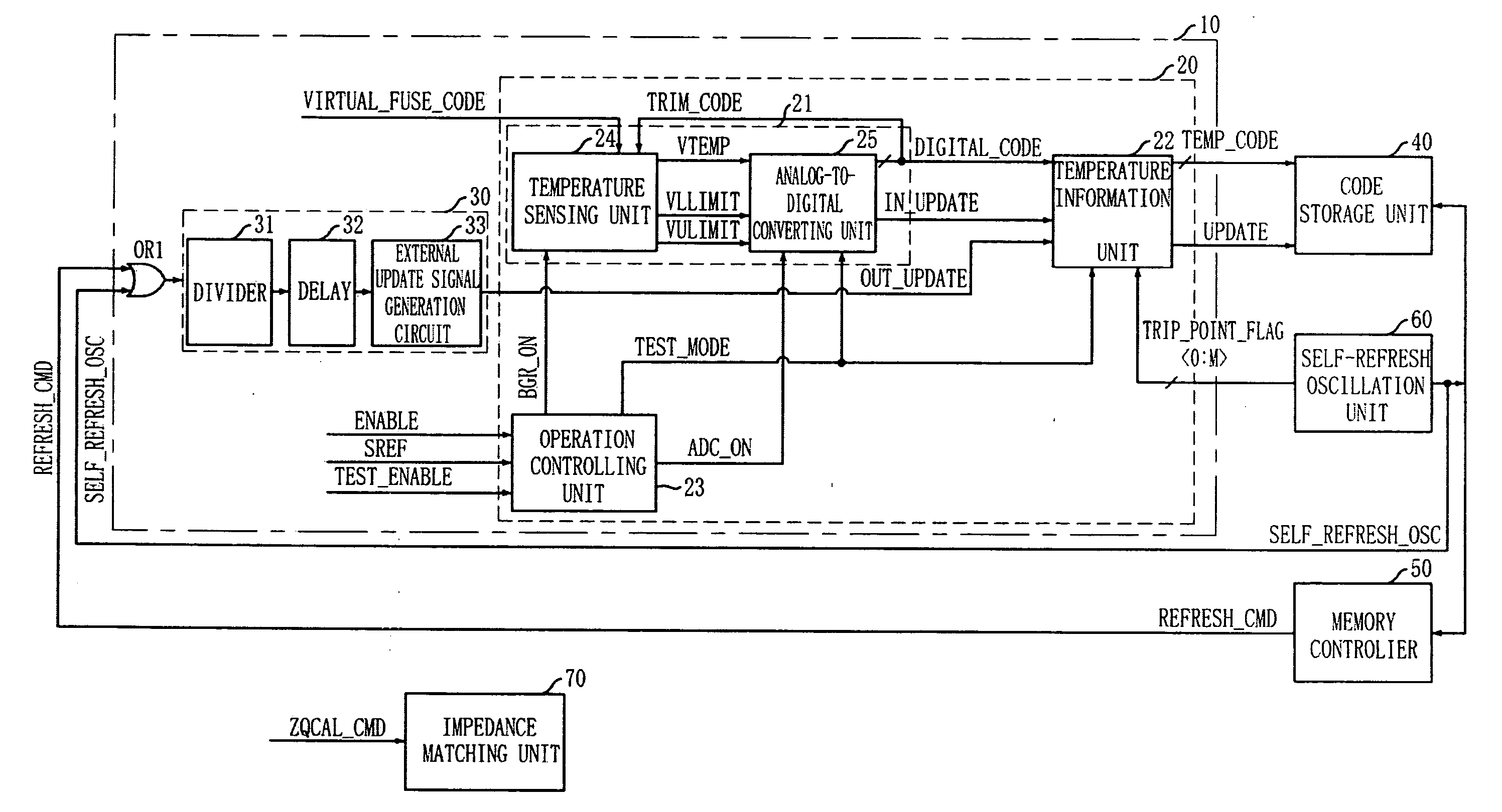
[0052]FIG. 3 is a block diagram of an ODTS for use in a semiconductor device in accordance with an embodiment of the present invention.
[0053]The ODTS of the present invention includes a temperature information output unit 10 which generates temperature information by measuring an internal temperature of the semiconductor device, and updates the temperature information according to a refresh period.
[0054]In detail, the temperature information output unit 10 includes a temperature information code generation unit 20 and an external update signal output unit 30.
[0055]The temperature information code generation unit 20 measures the internal temperature of the semiconductor device to generate a tempe...
PUM
| Property | Measurement | Unit |
|---|---|---|
| temperature | aaaaa | aaaaa |
| temperature | aaaaa | aaaaa |
| temperature | aaaaa | aaaaa |
Abstract
Description
Claims
Application Information