Linear guide apparatus

Active Publication Date: 2008-04-10
NSK LTD
View PDF16 Cites 22 Cited by
  • Summary
  • Abstract
  • Description
  • Claims
  • Application Information

AI Technical Summary

Benefits of technology

[0009] The invention has been made in view of the problems that have been described above. An object thereof is to provide a linear guide apparatus which can facilitate the replacement of lubricant application members without requiring many labor hours and much time. In addition, another object of the invention is to provide a slide table apparatus which can facilitate the

Problems solved by technology

In the linear guide apparatus described above, since the rolling elements roll on the rolling element rolling raceway surfaces when the slider moves relatively in the longitudinal direction of the guide rail, there is caused an inherent problem that lubricant needs to be refilled periodically via a grease nipple in order to prevent the seizing of the rolling elements.
However, in the event that the amount of lubricant contained in the lubricant application member is decreased to a low level, the lubricant application member in use needs to be replaced with another lubricant application member, although the frequency at which such a replacement occurs is not high.
Due to this, with the linear guide apparatus that has been described above, there has been an inherent problem that many labor hours and much time are required to replace lubricant application members.
In this case, as is shown in FIG. 58, in the event that a slide table b of a slider table system is fixed to an upper surface portion of a slider main body a, when attempting to replace a lubricant application member c whose lubricant content is low with a new lubr

Method used


Image

  • Linear guide apparatus
  • Linear guide apparatus
  • Linear guide apparatus

Examples


first embodiment

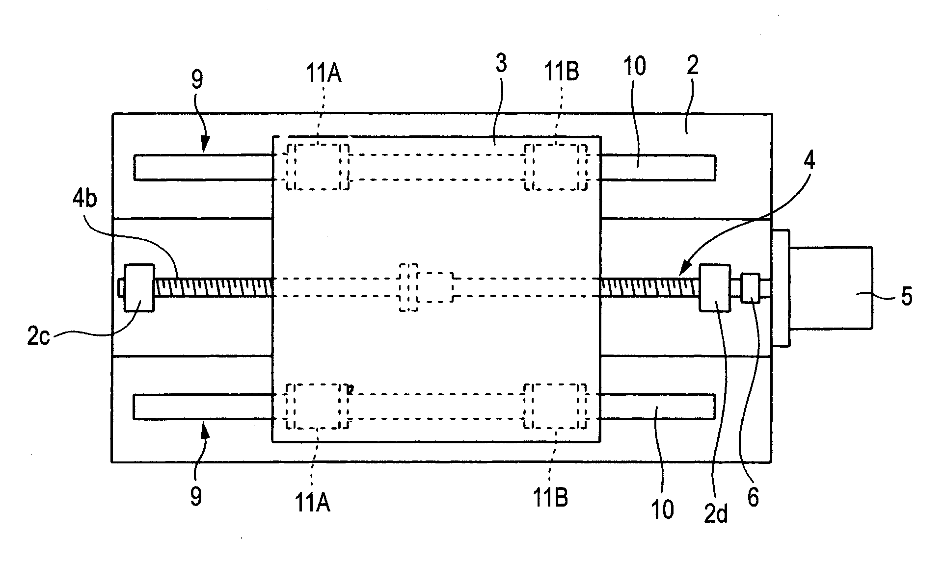
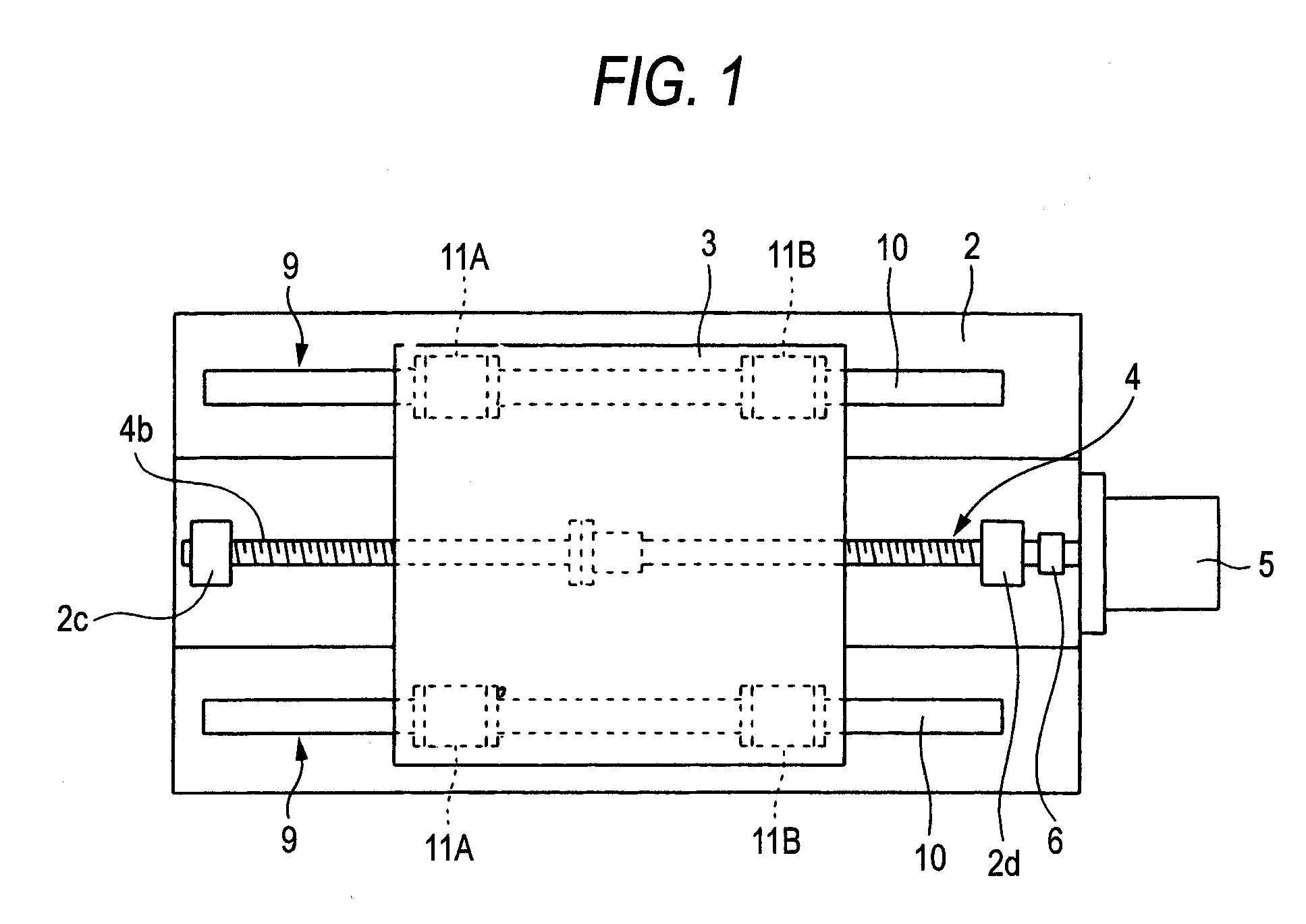
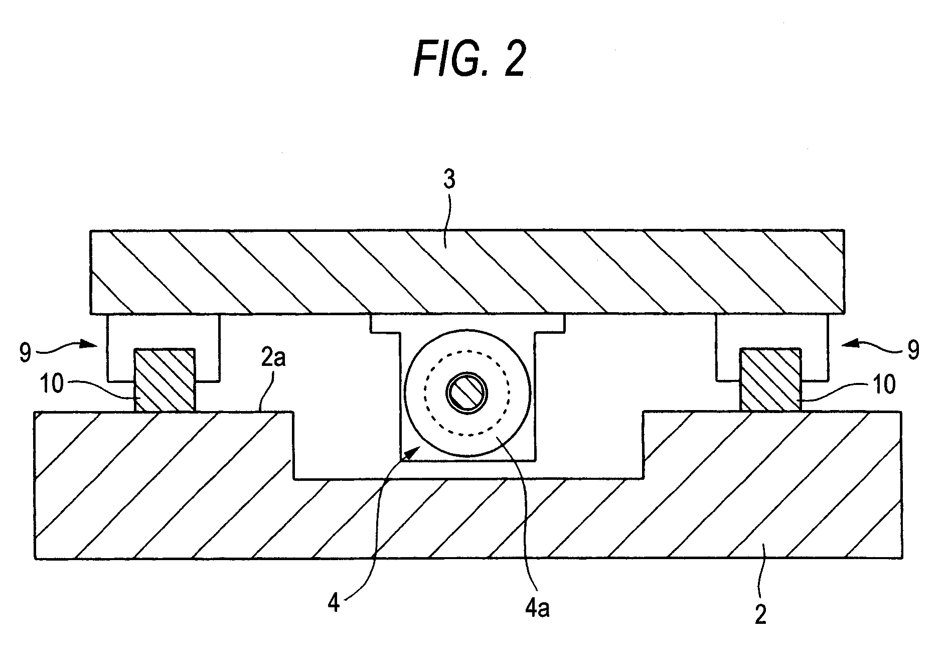
[0180] FIGS. 1 to 11 are drawings which show the invention, and slide table apparatus 1 includes a base 2 and a slide table 3.

[0181] The slide table 3 has a lower surface portion 3a (refer to FIG. 2) which faces an upper surface portion of the base 2, and a nut 4a for a ball screw 4 which drives to feed the slide table 3 is fixed to the lower surface portion 3a of the slide table 3.

[0182] The ball screw 4 includes a screw shaft 4b which is brought into thread engagement with the nut 4a via a large number of balls (not shown). This screw shaft 4b is rotatably supported in locations near to end portions thereof by bearings 2c, 2d which are provided on the base 2, and a motor shaft of a ball screw driving motor 5 (refer to FIG. 1) for driving the screw shaft 4b is connected to one end portion of the screw shaft 4b via a coupling 6.

[0183] The ball screw driving motor 5 is fixed to the base 2, and a plurality of linear guide apparatuses 9 for guiding the side table 3 in an axial direct...

second embodiment

[0197] In the embodiment that has been described heretofore, while the side seal fixing unit made up of the U-shaped pressing member 25 which presses and holds the side seal 20 against the lubricant application member 22, the pivot shaft 26 which is provided at the one end portion of the pressing member 25 in such a manner as to extend along the height direction of the guide rail 10 and the support plate 27 which supports rotatably the pressing member 25 via the pivot shaft 26 is used as the side seal fixing unit for fixing the side seal 20 to the end cap 17, as in a second embodiment shown in FIG. 14, a side seal fixing member 45 may be used which is made up of a U-shaped pressing member 46 which presses and holds a side seal 20 against a lubricant application member 22 and a lubricant application member receiving member 48 having on left and right side surface portions thereof recessed portions 49 which function as locking portions which fit on raised portions (or recessed portion...

third embodiment

[0199] Next, referring to FIGS. 15 to 24, the invention will be described.

[0200]FIG. 15 is a side view of a linear guide apparatus according to a third embodiment of the invention, FIG. 16 is a front view of the linear guide apparatus according to the same embodiment, and FIG. 17 is a sectional view taken along the line XVII-XVII in FIG. 15, and the linear guide apparatus according to the third embodiment includes a guide rail 10 and a slider 11.

[0201] The guide rail 10 is formed in a straight line, two rolling element rolling grooves 13 as rolling element raceway surfaces are formed along a longitudinal direction of the guide rail on each of left and right side surface portions of the guide rail 10.

[0202] The rolling element rolling grooves 13 face four rolling element rolling grooves 16 which are formed on a bearing 15 of the slider 11, respectively. A large number of rolling elements 12 are incorporated between the rolling element grooves 13 and the rolling element grooves 16. ...


PUM


Abstract

A side seal fixing unit 24, which is made up of a U-shaped pressing member 25 which presses and holds a side seal 20 against a lubricant application member 22, a pivot shaft 26 provided at one end portion of the pressing member 25 along a height direction of a guide rail 10 and a support plate 27 which supports rotatably the pressing member 25 via the pivot shaft 26 is provided between an end cap 17 and the lubricant application member 22.

Description

BACKGROUND OF THE INVENTION [0001] 1. Field of the Invention [0002] The present invention relates to a linear guide apparatus which guides a rectilinearly reciprocating object along its moving direction. [0003] 2. Description of Related Art [0004] Among linear guide apparatuses used in machine tools, there is a linear guide apparatus which has a rectilinearly formed guide rail and a slider which moves relatively in a longitudinal direction of the guide rail and has a large number of rolling elements incorporated in an interior thereof. In addition, the slider has a slider main body, and the slider main body is configured to include a bearing having a plurality of rolling element raceway surfaces which face rolling element raceway surfaces formed on left and right side surface portions of the guide rail, a pair of end caps which are mounted on one end and the other end of the bearing, a plurality of return guides incorporated in each of the end caps and the large number of rolling el...

Claims


Application Information

Patent Timeline
IPC IPC(8): B23Q1/62F16C33/00
CPCF16C29/008F16C33/6622F16C29/086F16C29/0671
Inventor HAYASHI, EIJIKATO, SOICHIRO
Owner NSK LTD
Why Eureka
Try Eureka