Honeycomb unit and honeycomb structure

a honeycomb and unit technology, applied in the direction of separation process, physical/chemical process catalyst, filtration separation, etc., can solve the problems of contaminant harmful to the environment and the human body

Active Publication Date: 2008-04-10
IBIDEN CO LTD
View PDF56 Cites 57 Cited by
  • Summary
  • Abstract
  • Description
  • Claims
  • Application Information

AI Technical Summary

Problems solved by technology

Recently, particulates, such as soot, contained in exhaust gases that are discharged from internal combustion engines for vehicles such as a bus,...

Method used


Image

  • Honeycomb unit and honeycomb structure
  • Honeycomb unit and honeycomb structure
  • Honeycomb unit and honeycomb structure

Examples


example 1

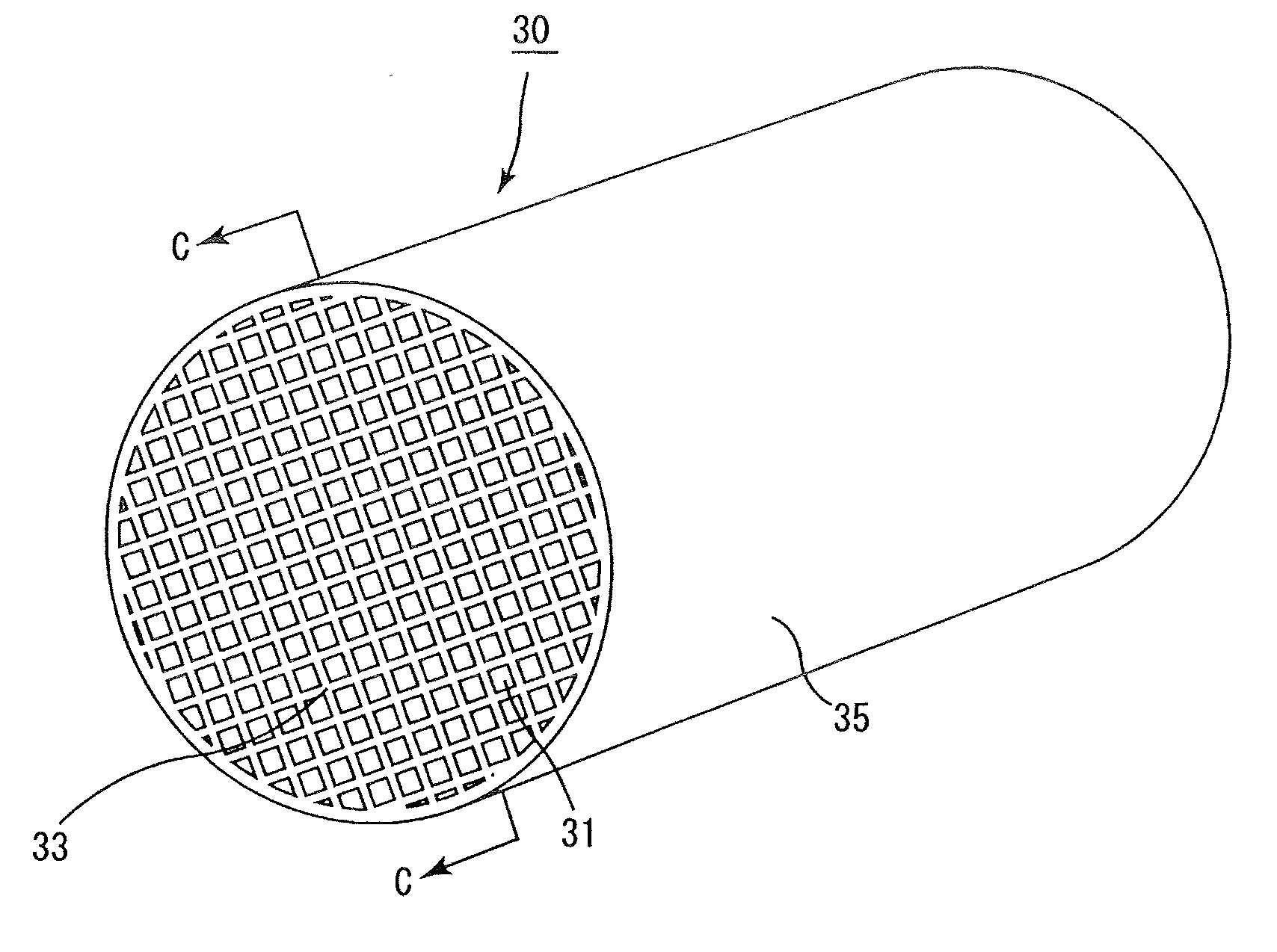
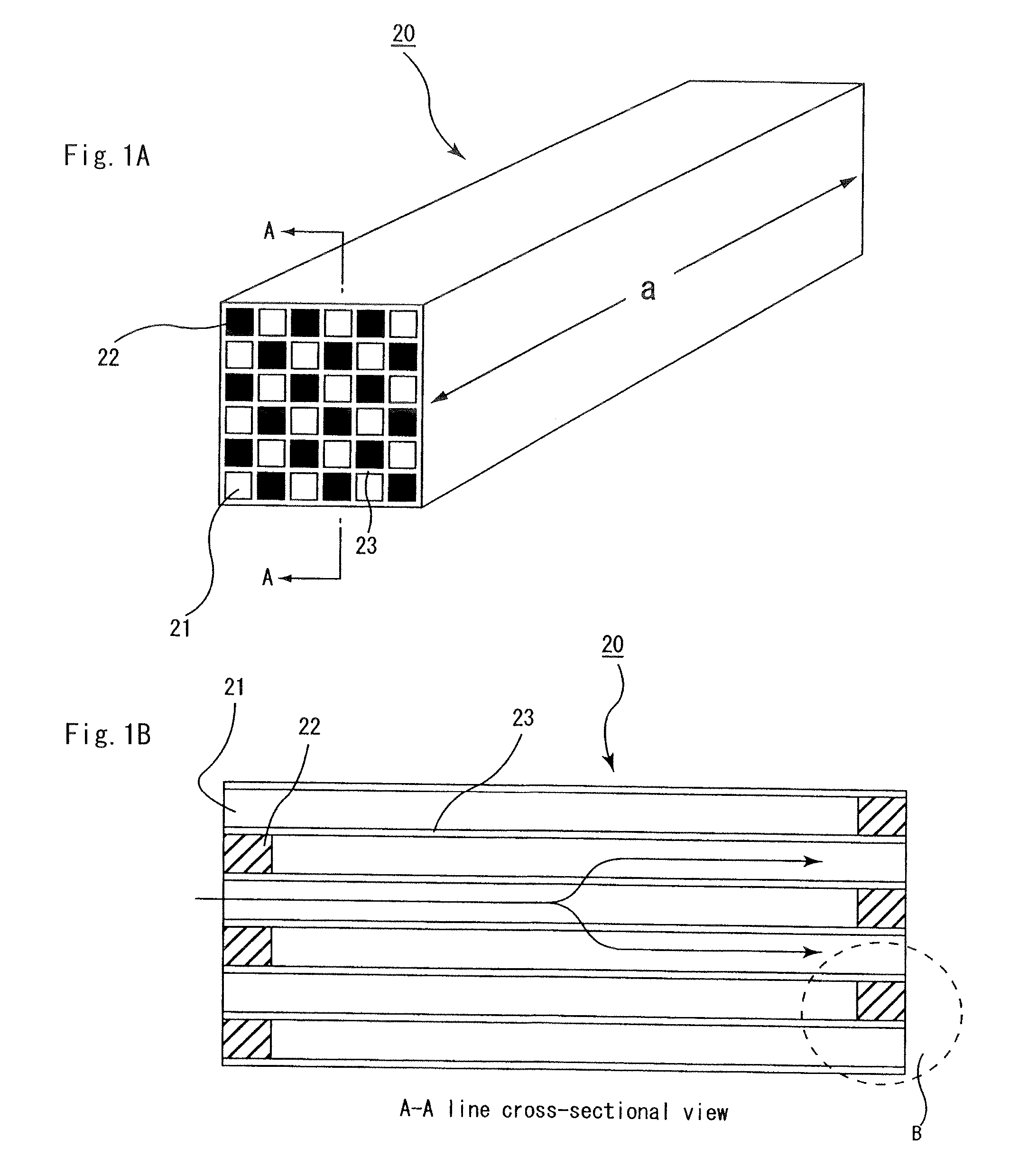
[0180] Coarse powder of α-type silicon carbide having an average particle diameter of 22 μm (52.2% by weight) and fine powder of α-type silicon carbide having an average particle diameter of 0.5 μm (22.4% by weight) were wet-mixed, and to the resulting mixture were added and kneaded 4.8% by weight of acrylic resin, 2.6% by weight of an organic binder (methyl cellulose), 2.9% by weight of a lubricant (UNILUB made by NOF Corp.), 1.3% by weight of glycerin and 13.8% by weight of water to obtain a mixed composition, and this was then extrusion-molded to manufacture a raw molded body having the same shape as the honeycomb unit 20 shown in FIG. 1A and FIG. 1B, except that the end portion of the cell was not sealed.

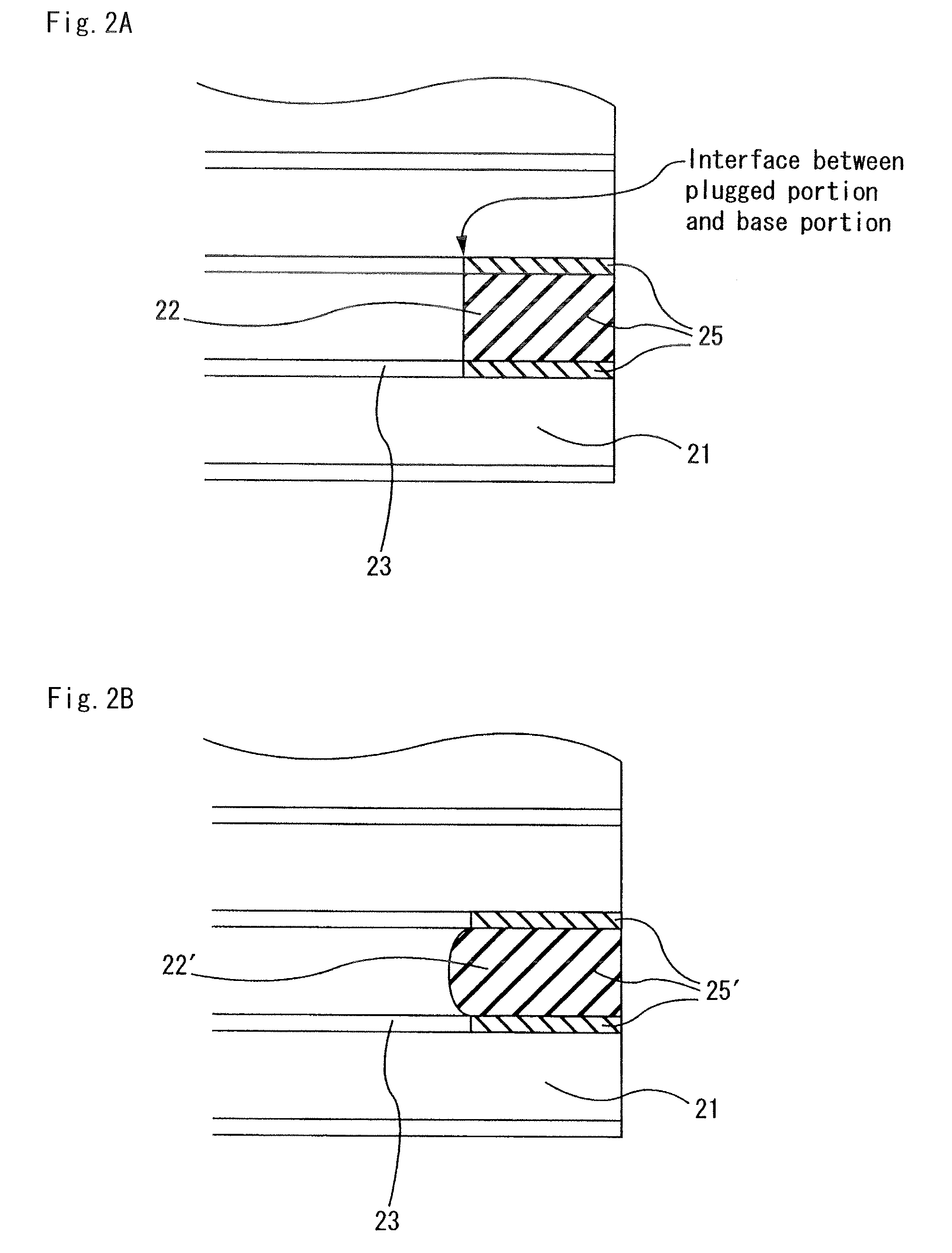
[0181] Next, after the above-mentioned raw molded body had been dried by using a micro-wave drier or the like to prepare a ceramic dried body, predetermined cells were filled with a plug material paste having the composition as described below. In the present process, upon inje...

examples 2 to 12

[0187] A separate-type honeycomb structure was manufactured through the same processes as in Example 1, except that the length of the honeycomb unit, and the length of the plugged portion were set to the values shown in Table 1-1.

example 13

[0188] A separate-type honeycomb structure was manufactured through the same processes as in Example 1, except that the size of the honeycomb unit was set to 40 mm×40 mm×250 mm, and the length of the plugged portion was set to 6.0 mm.


PUM

PropertyMeasurementUnit
Densityaaaaaaaaaa
Volumeaaaaaaaaaa
Lengthaaaaaaaaaa

Abstract

A honeycomb unit includes a plurality of walls and a plurality of cells. The plurality of cells are defined by the plurality of walls and extend along a longitudinal direction of the honeycomb unit. Each of the plurality of cells has opposite first and second end portions along the longitudinal direction. Either one of the first and second end portions is sealed. X and Y satisfy a following relationship, 100/3·X+5≦Y≦100/3·X+40, wherein Y is a ratio of a weight of an unsealed region in said cells to a weight of a sealed region in said cells and X is a ratio of a length in the longitudinal direction of said honeycomb unit to an area of a cross-section perpendicular to the longitudinal direction of said honeycomb unit. X is at least about 0.1 and at most about 0.26.

Description

CROSS-REFERENCE TO RELATED APPLICATIONS [0001] This application is a continuation application of PCT / JP2006 / 316622 filed on Aug. 24, 2006, which claims priority of Japanese Patent Application No. 2005-297858 filed on Oct. 12, 2005. The contents of these applications are incorporated herein by reference in their entirety.BACKGROUND OF THE INVENTION [0002] 1. Field of the Invention [0003] The present invention relates to a honeycomb unit, and a honeycomb structure having the honeycomb unit as a component member. [0004] 2. Discussion of the Background [0005] Recently, particulates, such as soot, contained in exhaust gases that are discharged from internal combustion engines for vehicles such as a bus, a truck and the like, construction equipment and the like, have raised serious problems as contaminants harmful to the environment and the human body. [0006] For this reason, various applications in which honeycomb structures, which are made from porous ceramics, are used as filters for c...

Claims


Application Information

Patent Timeline
IPC IPC(8): B01D39/20B32B3/12
CPCB01D39/2068Y10T428/24149B01D46/2425B01D46/2429B01D46/244B01D46/2455B01D46/2459B01D46/2466B01D2046/2496B01D2273/20B01J35/002B01J35/04F01N3/0222F01N2330/48B01D46/0063B01D46/2498B01D46/84B01D46/2484B01D46/2482B01D46/2476B01D46/2478B01D39/00
Inventor KUNIEDA, MASAFUMIFUJITA, YUKI
Owner IBIDEN CO LTD
Why Eureka
Try Eureka