

Ppa/fluoropolymer pipe
a fluoropolymer pipe and fluoropolymer technology, applied in the direction of rigid pipes, flexible pipes, applications, etc., can solve the problems of transmission fluid damage, automatic gearbox damage, and no structure found to be completely satisfactory, and achieve the effect of low pipe permeability, good protection against external aggression, and good permeability of pipes
- Summary
- Abstract
- Description
- Claims
- Application Information
AI Technical Summary
Benefits of technology
Problems solved by technology
Method used
Image

Examples
first embodiment
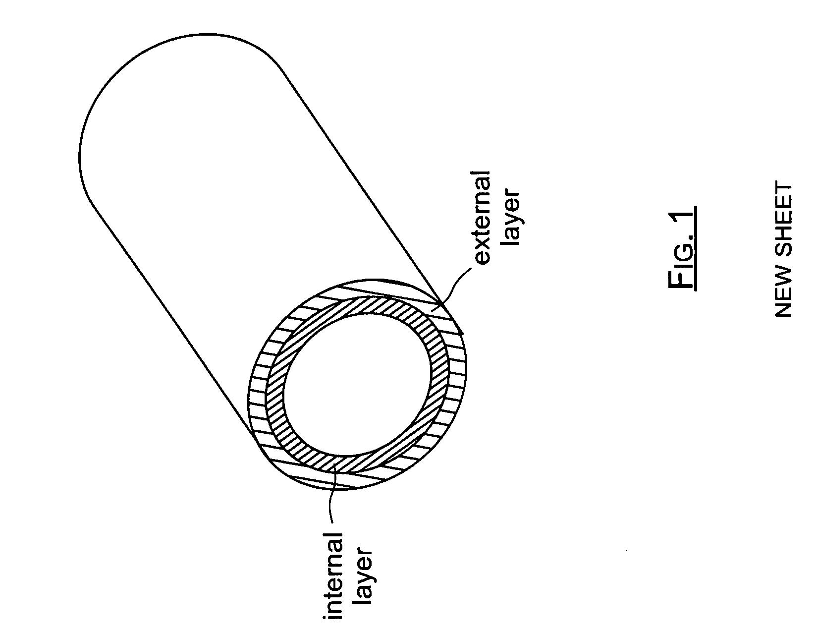
[0009]In a first embodiment, the pipe comprises one layer of polyphthalamide as an outer layer and one layer of fluoropolymer as an inner layer.
[0010]Suitable fluoropolymers comprise, in particular: polyvinylidene fluoride (PVDF); ethylene tertrafluoroethylene (ETFE); ethylene fluoroethylene perfluoride (EFEP); polytetrafluoroethylene (PTFE); fluoroethylene propylene (FEP); perfluoroalkoxy (PFA); ethylene chlorotrifluoroethylene (ECTFE), . . . .
[0011]By way of example, the fluoropolymer may be a Teflon FEP from the supplier DuPont de Nemours, and the polyphthalamide may be that produced under the trademark Amodel by the supplier Solvay.
[0012]This pipe is particularly well adapted to transporting fuel and in particular alcohol-containing fuels since the overall performance of the materials used is very stable in a medium containing alcohol.
[0013]In a variant, when the adhesive properties of the pipe are not sufficient for its conditions of use, it is possible to add a bonding layer b...
second embodiment
[0016]In a second embodiment, the pipe in accordance with the invention has an inner layer made of polyphthalamide (PPA) with thickness lying in the range 1 mm to 1.5 mm.
[0017]The pipe also includes an outer layer made of a fluoropolymer and preferably a terpolymer of tetrafluoroethylene, hexafluoropropylene, and vinylidene fluoride (THV). Other fluoropolymers can be used, such as: polyvinylidene fluoride (PVDF); ethylene tertrafluoroethylene (ETFE); ethylene fluoroethylene perfluoride (EFEP); polytetrafluoroethylene (PTFE); fluoroethylene propylene (FEP); perfluoroalkoxy (PFA); ethylene chlorotrifluoroethylene (ECTFE), . . . . The outer layer has a thickness of about 0.2 mm.
[0018]This thickness ratio is the optimum solution for making a pipe in accordance with the second embodiment of the invention.
[0019]The pipe in accordance with the invention is made by extrusion, and the outer layer is in direct contact with the inner layer. This is made possible by the good properties of mutua...
PUM
| Property | Measurement | Unit |
|---|---|---|
| Thickness | aaaaa | aaaaa |
| Thickness | aaaaa | aaaaa |
| Thickness | aaaaa | aaaaa |
Abstract
Description
Claims
Application Information