Liquid crystal composition and liquid crystal display device

a liquid crystal composition and display device technology, applied in liquid crystal compositions, thin material processing, chemistry apparatus and processes, etc., can solve the problems of long service life and small electric power consumption of devices, and achieve the effects of increasing optical anisotropy, increasing dielectric anisotropy, and reducing the minimum temperatur

Inactive Publication Date: 2008-04-10
JNC PETROCHEM CORP +1
View PDF20 Cites 21 Cited by
  • Summary
  • Abstract
  • Description
  • Claims
  • Application Information

AI Technical Summary

Benefits of technology

[0031]The invention further includes: (1) the composition described above, wherein the composition further includes an optically active compound; (2) the composition described above, wherein the composition further includes an additive, such as an antioxidant, an ultraviolet light absorbent and / or an antifoaming agent; (3) an AM device including the composition described above; (4) a device having a TN, ECB, OCB or IPS, including the composition described above; (5) a device of a transmission type, including the composition described above; (6) use of the composition described above as a composition having a nematic phase; and (7) use as an optically active composition by adding an optically active compound to the composition described above.
[0032]The composition of the invention will be explained in the following order. First, the constitution of component compounds in the composition will be explained. Second, the main characteristics of the component compounds and the main effects of the compounds on the composition will be explained. Third, a desirable ratio of the component compounds and the basis thereof will be explained. Fourth, a desirable embodiment of the component compounds will be explained. Fifth, examples of the component compound will be shown. Sixth, additives that may be added to the composition will be explained. Seventh, the preparation methods of the component compound will be explained. Lastly, use of the composition will be explained.
[0033]First, the constitution of component compounds in the composition will be explained. The composition of the invention is classified into the composition A and the composition B. The composition A may further include other compounds such as another liquid crystal compound, an additive, an impurity, and so forth. This liquid crystal compound is different from the compound (1-1), the compound (1-2), the compound (2), the compound (3-1) and the compound (3-2). Such a liquid crystal compound is mixed with the composition for the purpose of adjusting the characteristics of the composition. Among the liquid crystal compounds, an amount of a cyano compound is desirably small from the viewpoint of stability to heat or ultraviolet light. The amount of a cyano compound is more desirably approximately 0% by weight. The additive includes an optically active compound, an antioxidant, an ultraviolet light absorbent, a coloring matter, an antifoaming agent and so forth. The impurity is a compound and so forth contaminated in the process such as the synthesis of a component compound and so forth.
[0034]The composition B essentially consists of the compounds selected from the compound (1-1), the compound (1-2), the compound (2), the compound (3-1) and the compound (3-2). The term “essentially” means that the composition does not contain a liquid crystal compound which is different from these compounds. The term “essentially” also means that the composition may further contain the additive, the impurity, and so forth. The components of the composition B are fewer than those of the composition A. The composition B is preferable to the composition A from the viewpoint of costs. The composition A is preferable to the composition B, because characteristics of the composition A can be further adjusted by mixing with other liquid crystal compounds.
[0035]Second, the main characteristics of the component compounds and the main effects of the compounds on the composition will be explained. The main characteristics of the component compounds are summarized in Table 2. In Table 2, the symbol “L” represents large or high, the symbol “M” represents a middle degree, and the symbol “S” represents small or low. The symbols L, M and S are classifications based on qualitative comparison among the component compounds.
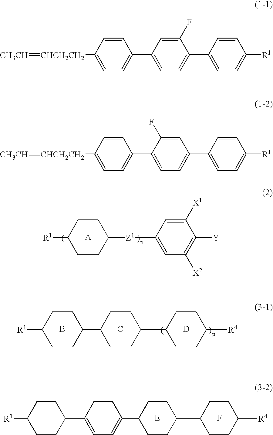
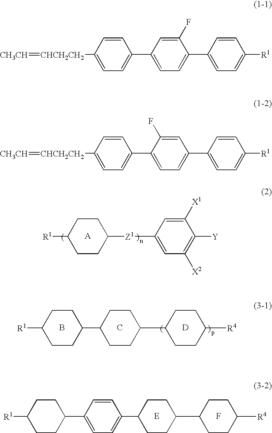
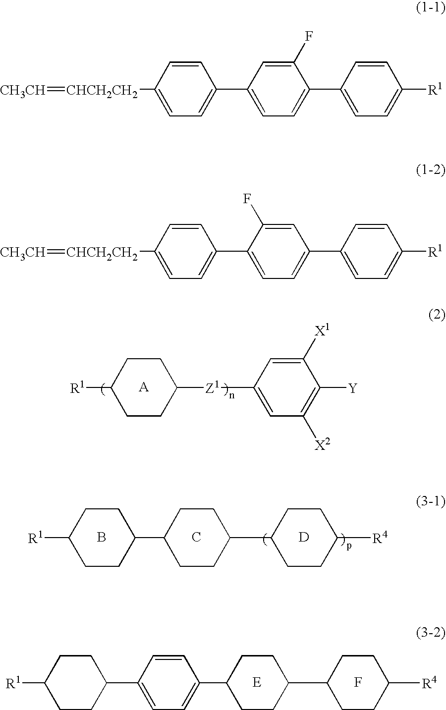
[0036]The main effects of the component compounds to the characteristics of the composition upon mixing the component compounds to the composition are as follows. The compounds (1-1) and (1-2) increase the optical anisotropy. The compound (2) increases the dielectric anisotropy. The compound (3-1) decreases the minimum temperature and decreases the viscosity. The compound (3-2) increases the maximum temperature.

Problems solved by technology

A large dielectric anisotropy of the composition contributes to a low threshold voltage, a small electric power consumption and a large contrast ratio.
In the case where the stability is high, the device has a long service life.

Method used


Image

  • Liquid crystal composition and liquid crystal display device
  • Liquid crystal composition and liquid crystal display device
  • Liquid crystal composition and liquid crystal display device

Examples


example 1

[0084]The composition of Example 1 has a small rotation viscosity as compared to the composition of Comparative Example 1.

1V2-BB(F)B-1(1-1-1)3%1V2-BB(F)B-2(1-1-1)3%1V2-BB(F)B-3(1-1-1)3%3-HBB(F,F)-F(2-1-1)6%3-BB(F,F)XB(F,F)-F(2-4-1)21%3-HH-V(3-1-1-1)33%3-HH-V1(3-1-1-1)11%V-HHB-1(3-1-4-1)12%V2-HHB-1(3-1-4-1)3%5-HBB(F)B-2(3-2-3-1)5%

[0085]NI=79.4° C.; Tc≦−20° C.; Δn=0.111; Δ∈=4.3; Vth=2.04 V; γ1=50.2 mPa·s; τ=6.0 ms; VHR-1=99.1%; VHR-2=98.3%; VHR-3=98.1%.

example 2

[0086]The composition of Example 2 has a small rotation viscosity as compared to the composition of Comparative Example 1.

1V2-BB(2F)B-1(1-2-1)3%1V2-BB(2F)B-2(1-2-1)3%1V2-BB(2F)B-3(1-2-1)4%3-BB(F)B(F,F)-F(2-2-1)7%3-BB(F,F)XB(F,F)-F(2-4-1)20%3-HH-V(3-1-1-1)35%5-HH-V(3-1-1-1)5%3-HH-V1(3-1-1-1)10%V-HHB-1(3-1-4-1)5%5-HBBH-3(3-2-1-1)5%5-HB(F)BH-3(3-2-2-1)3%

[0087]NI=76.6° C.; Tc≦−20° C.; Δn=0.110; Δ∈=4.4; Vth=2.00 V; γ1=48.2 mPa·s; τ=5.8 ms; VHR-1=99.1%; VHR-2=98.2%; VHR-3=98.1%.

example 3

[0088]The composition of Example 3 has a small rotation viscosity as compared to the composition of Comparative Example 1.

1V2-BB(F)B-1(1-1-1)3%1V2-BB(F)B-2(1-1-1)3%1V2-BB(2F)B-1(1-2-1)3%1V2-BB(2F)B-2(1-2-1)3%1V2-BB-F(2)5%3-BB(F,F)XB(F,F)-F(2-4-1)20%3-HHB-CL(2-6-1)4%3-HBB-F(2-7-1)4%3-HBEB(F,F)-F(2-8-1)3%3-HH-V(3-1-1-1)30%3-HH-V1(3-1-1-1)10%3-HHB-1(3-1-4-1)7%5-HBB(F)B-3(3-2-3-1)5%

[0089]NI=80.6° C.; Tc≦−20° C.; Δn=0.121; Δ∈=4.6; Vth=1.94 V; γ1=51.3 mPa·s; τ=6.1 ms; VHR-1=99.1%; VHR-2=98.2%; VHR-3=98.2%.


PUM

PropertyMeasurementUnit
temperatureaaaaaaaaaa
frequencyaaaaaaaaaa

Abstract

A liquid crystal composition having a nematic phase that includes three components, wherein the first component is at least one compound selected from the group of compounds represented by formulas (1-1) and (1-2), the second component is at least one compound selected from the group of compounds having a group represented by formula (2), and the third component is at least one compound selected from the group of compounds represented by formulas (3-1) and (3-2):
wherein R1 and R4 are each independently alkyl having 1 to 12 carbons, alkoxy having 1 to 12 carbons, alkenyl having 2 to 12 carbons, or alkenyl having 2 to 12 carbons in which arbitrary hydrogen is replaced by fluorine; ring A is independently 1,4-cyclohexylene, 1,3-dioxane-2,5-diyl, 1,4-phenylene, 3-fluoro-1,4-phenylene, 3,5-difluoro-1,4-phenylene, or 2,5-pyrimidine; ring B, ring C, ring D and ring F are each independently 1,4-cyclohexylene or 1,4-phenylene; ring E is 1,4-cyclohexylene, 1,4-phenylene or 3-fluoro-1,4-phenylene; Z1 is a single bond, ethylene, carbonyloxy, or difluoromethyleneoxy; X1 and X2 are each independently hydrogen or fluorine; Y is fluorine, chlorine or trifluoromethoxy; n is 1, 2, or 3; and p is 0 or 1.

Description

CROSS REFERENCE TO RELATED APPLICATIONS[0001]This application claims priority under 35 U.S.C. § 119 to Japanese Patent Application No. JP 2006-273693, filed Oct. 5, 2006, which application is expressly incorporated herein by reference in its entirety.BACKGROUND OF THE INVENTION[0002]1. Field of the Invention[0003]The invention relates to a liquid crystal composition suitable for use in an active matrix (AM) device, and an AM device including the composition. More specifically, the invention relates to a liquid crystal composition having a positive dielectric anisotropy, and also relates to a device of a twisted nematic (TN) mode, an optically compensated bend (OCB) mode or an in-plane switching (IPS) mode.[0004]2. Related Art[0005]In a liquid crystal display device, classification based on an operating mode of liquid crystals includes phase change (PC), twisted nematic (TN), super twisted nematic (STN), electrically controlled birefringence (ECB), optically compensated bend (OCB), i...

Claims


Application Information

Patent Timeline
Patent Type & Authority Applications(United States)
IPC IPC(8): C09K19/12
CPCC09K19/44C09K2019/0448C09K2019/0466C09K2019/123C09K2019/2042C09K2019/3004Y10T428/10C09K2019/301C09K2019/3016C09K2019/3019C09K2019/3021C09K2019/3025C09K2019/3083C09K2019/3009C09K2323/00
Inventor SAITO, MASAYUKIGOTO, SHUICHIHIRAOKA, TAKASHI
Owner JNC PETROCHEM CORP
Why Eureka
Try Eureka