
Power Converter for Led Large Area Light Source Lamp

a technology of power converter and large area light source, which is applied in the direction of process and machine control, printed circuit non-printed electric components association, instruments, etc., can solve the problems of high output impedance, affecting the current supply to the load, and mainly limited maximum operating frequency, so as to achieve stable behavior of the power converter

Inactive Publication Date: 2008-04-10
SIGNIFY HLDG BV
View PDF12 Cites 39 Cited by
  • Summary
  • Abstract
  • Description
  • Claims
  • Application Information

AI Technical Summary

Benefits of technology

The invention is a power converter that uses a resonant circuit to achieve a constant output current with variations in the load. The converter includes a transformer, a primary side winding, and a secondary side winding. The transformer has a mutual inductance and a leakage inductance. The leakage inductance is matched with the operating frequency, the capacitor, and the load to maintain a constant output current. The converter operates at a resonance frequency determined by the series capacitor and the leakage inductance. The resonant circuit has a high output impedance at the resonance frequency. The operating frequency, the capacitor, and the leakage inductance can be matched to achieve a stable output current behavior with respect to changes in the load. The converter can be used in a current source mode with a high output impedance. The leakage inductance can be realized by shifting the center of the primary or secondary winding of the transformer or by different dimensions of the winding. The technical effect of the invention is a self-regulating behavior of the output current with respect to changes in the load, achieved by a resonant circuit design that matches the leakage inductance with the operating frequency, the capacitor, and the load.

Problems solved by technology

Indeed, the current supplied to the load is affected by the load to a limited extend, only.
Operated at this basic resonance frequency, the power converter acts much like a current source at its secondary side, resulting in a high output impedance.
Indeed, the maximal operating frequency is mainly limited by the switching devices.
For this reason, an unlimited increase of the operating frequency is not possible at reasonable cost.

Method used


Image

  • Power Converter for Led Large Area Light Source Lamp
  • Power Converter for Led Large Area Light Source Lamp
  • Power Converter for Led Large Area Light Source Lamp

Examples


Embodiment Construction

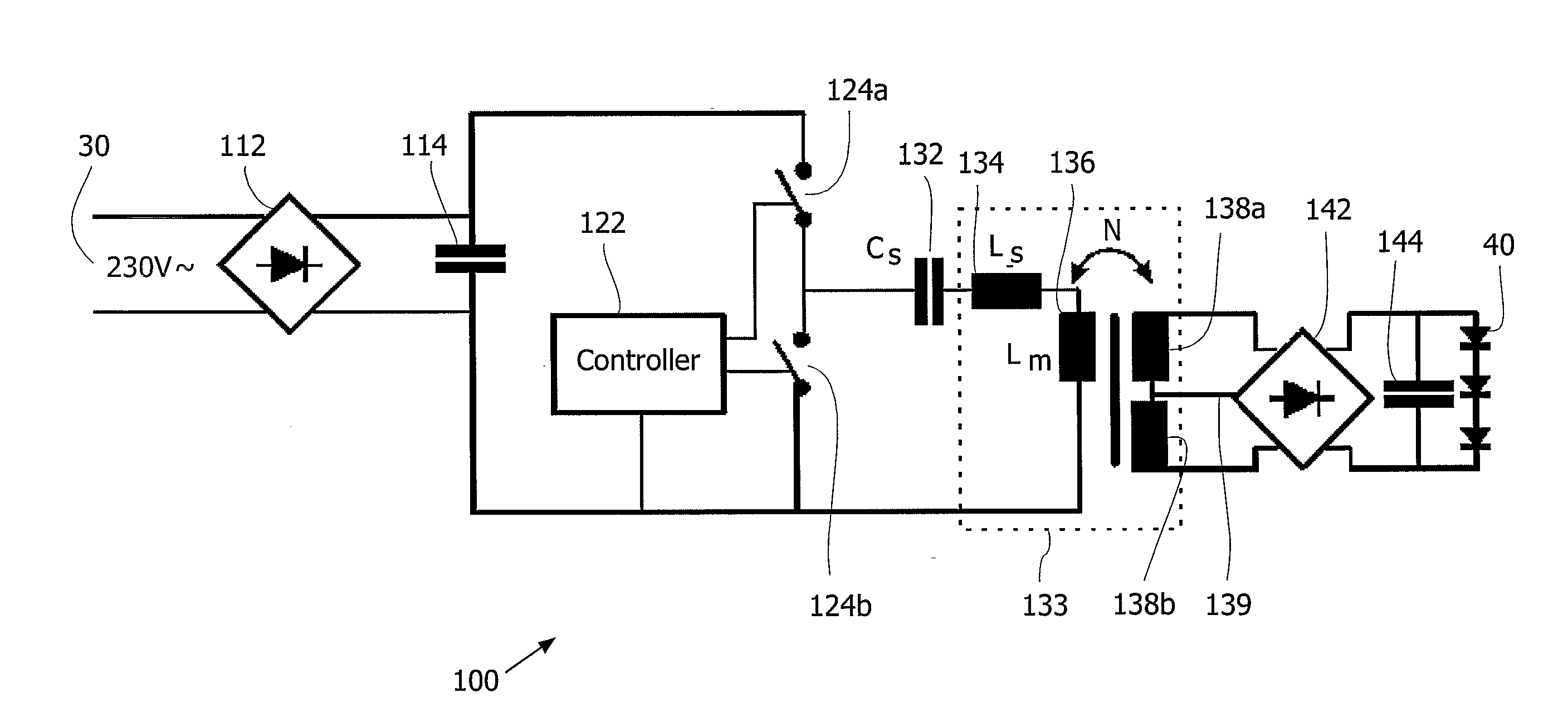
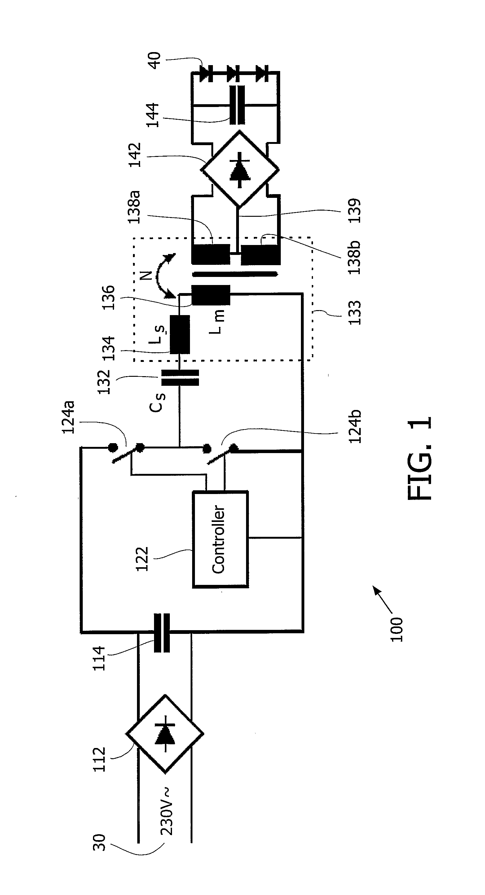
[0042]Referring now to FIG. 1, there is shown a schematic diagram of a power converter (100) for adapting the power supplied by a mains supply net (30) to the operating conditions of an electrical consumer (40). This adaptation comprises reduction of the voltage and rectifying an AC current supplied by the mains supply net (30) to a DC current required by the electrical consumer (40). The mains supply net may provide a 230V AC / 50 Hz voltage, such as provided by European mains supply networks, but may equally be a voltage provided by some other mains supply net, such as an United States mains supply net, i.e. a 110 V AC / 60 Hz voltage. In this embodiment, the electrical consumer (40) consists of several Light Emitting Diodes (LED's), connected in series. Due to their current-voltage characteristic, diodes tend to maintain a voltage at their terminals that is in the vicinity of their predetermined forward voltage. The intensity of a current flowing through a diode, on the other hand, i...


PUM


Abstract

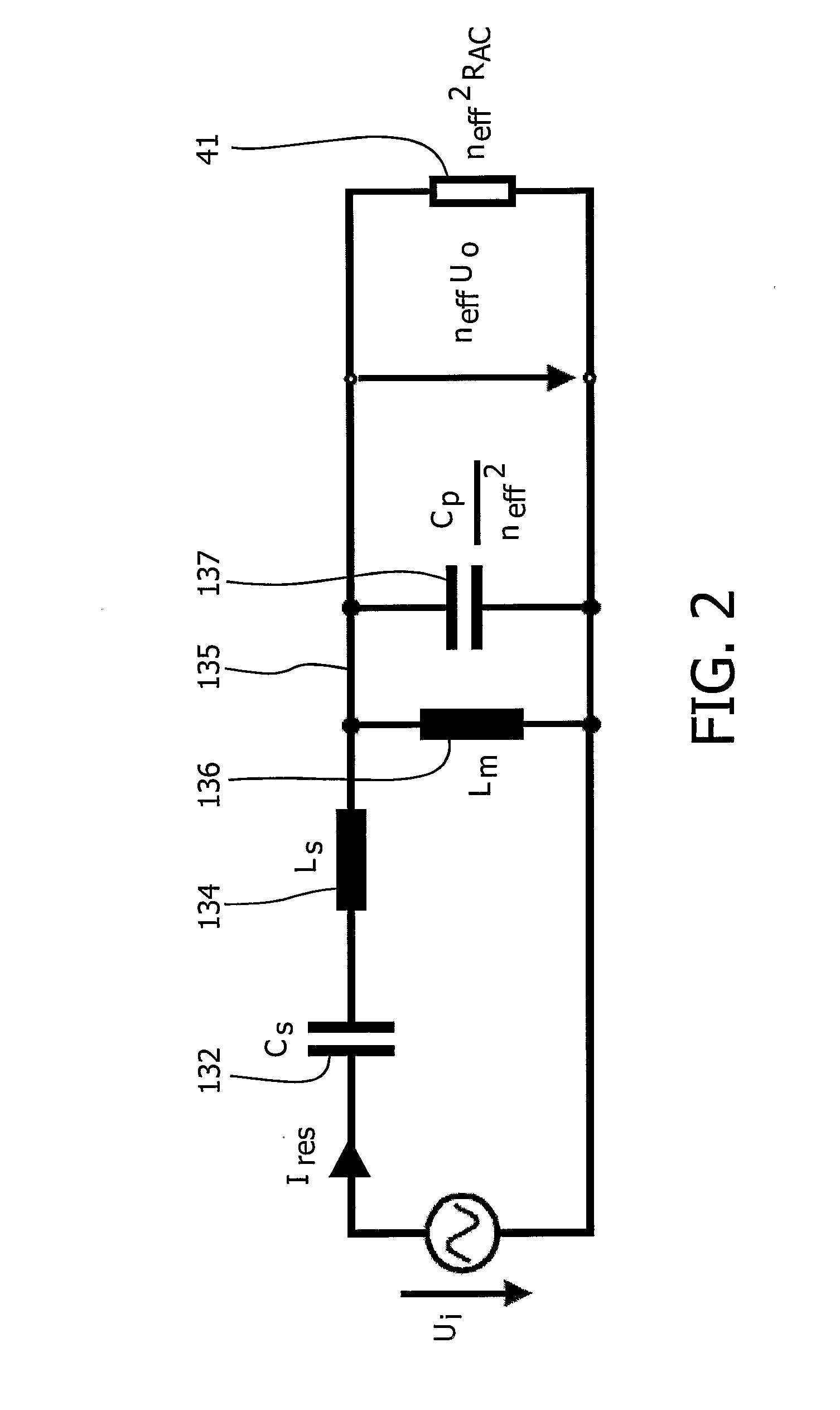
Power converter for receiving an input current at an input voltage and for providing an output current at an output voltage. The power converter comprises a transformer (133) having a primary (136) and at least one secondary (138) side, wherein the transformer shows a mutual inductivity Ls. The power converter further comprises at least one switching device (124a, 124b) being operated at an operating frequency ƒop at the primary side of said transformer, and a capacitor Cs at the primary side of the transformer. The capacitor forms a resonant circuit with the leakage inductivity Ls of said transformer, wherein said operating frequency, said capacitor Cs, said mutual inductivity Lm and said leakage inductivity Ls are matched such that the effective value of the output current is substantially constant with respect to variations of a load being traversed by said output current by using resonance principles and operating the power converter in a current source mode.

Description

FIELD OF THE INVENTION[0001]The present invention relates generally to power converters, and more particularly to a power converter for a Large Area Light Source (LALS) lamp comprising Light Emitting Diodes (LED) as illuminants. As a result, the converter is thin enough for integration in thin devices.BACKGROUND OF THE INVENTION[0002]Electronic industry faces an increasing pressure towards miniaturization and cost savings. Especially in the consumer electronics sector, manufacturers strive for being able to manufacture products for their clients as small, flat, and compact as possible.[0003]In the microelectronics domain, an enormous miniaturization, along with an automation of the manufacturing process could be achieved by integration of components in microchips. In the power electronics domain, construction volume and weight of circuits could be successfully reduced in the past, due to the development of switching mode power supplies (SMPS). In particular, the transfer of power us...

Claims


Application Information

Patent Timeline
Patent Type & Authority Applications(United States)
IPC IPC(8): H05B41/36H02M7/02H02M7/217
CPCH02M3/337H02M3/3376Y02B70/1433H05B33/0815Y02B20/347H05B33/0803Y02B20/30Y02B70/10H05B45/3725H02M3/33571H02M3/01
Inventor WAFFENSCHMIDT, EBERHARDNEUBERT, TOM
Owner SIGNIFY HLDG BV
Learn More