Inkjet recording system

a recording system and inkjet technology, applied in the direction of measuring apparatus components, instruments, printing, etc., can solve the problems of insufficient water resistance and weather resistance, shortening the life of the printer head, increasing the load applied to the actuator, etc., to achieve stable keeping and high quality

Inactive Publication Date: 2008-04-10
KYOCERA DOCUMENT SOLUTIONS INC
View PDF1 Cites 3 Cited by
  • Summary
  • Abstract
  • Description
  • Claims
  • Application Information

AI Technical Summary

Benefits of technology

[0023] According to this inkjet recording system, it is possible to stably keep discharge velocity of ink droplet discharged from the nozzle, and to form an image of high quality with little lines or uneven coloring caused by deviation at the time of landing of ink droplet under the influence of sheet conveying velocity, because an ink containing a pigment having a specific average volumetric particle diameter is used, and the relation formula between average surface roughness Ra of piezoelectric element and average volumetric particle diameter D of pigment falls within a specific range.

Problems solved by technology

However, such aqueous dye ink has the problem of insufficient water resistance and weather resistance.
However, with the increase of driving voltage, the load applied onto the actuator increases.
This is not desired because the life time of the printer head is shortened, and also from the viewpoint of energy saving.
However, when this liquid droplet discharge head is filled with pigment ink using a multi-nozzle liquid droplet discharge head in which a part of wall surface of pressure chamber is formed of a piezoelectric element, non-discharge nozzles occur more frequently compared to the case where dye ink is used, so that troubles such as jet disability, dot missing and disorder of printing occur, leading impairment in printing quality.
However, it was demonstrated that when pigment ink was discharged using the above-described multi-nozzle liquid droplet discharge head, the discharge velocity of pigment ink was smaller than that of dye ink, and hence the desired 9 m / s was not realized.
Therefore, lines or uneven coloring may significantly occur in association with deviation at the time of landing of ink droplet, so that image quality is impaired.

Method used


Image

  • Inkjet recording system
  • Inkjet recording system
  • Inkjet recording system

Examples


first embodiment

[0035] According to an inkjet recording system of the present embodiment, in a liquid droplet discharge head in which a part of wall surface of pressure chamber is formed of a piezoelectric element, arithmetic average surface inclination Δa (mrad) of lateral face of pressure chamber of the piezoelectric element satisfies Δa≦1050, and average volumetric particle diameter D(nm) of pigment contained in ink satisfies 80≦D≦200. Preferably, arithmetic average surface inclination Δa of lateral face of pressure chamber of the piezoelectric element and average volumetric particle diameter D of the pigment satisfy the above formula (1).

[0036] The present invention is based on the new findings: (a) when ink containing pigments having different average volumetric particle diameters are charged into a multi-nozzle liquid droplet discharge head incorporating a piezoelectric element having a specific average surface inclination, ink charging ratio differs depending on the difference in average vo...

second embodiment

[0059] According to an inkjet recording system according to this embodiment, in a liquid droplet discharge head in which a part of wall surface of pressure chamber is formed of a piezoelectric element, average volumetric particle diameter D(nm) of pigment contained in ink satisfies 80≦D≦200, and arithmetic surface roughness (Ra) of the piezoelectric element surface constituting a part of wall surface of the pressure chamber, and average volumetric particle diameter (D) satisfy the above formula (2).

[0060] The present invention is based on the new findings: (a) when ink containing pigments having different average volumetric particle diameters is discharged by using a multi-nozzle type liquid droplet discharge head incorporating a piezoelectric element of a specific surface roughness, discharge velocity of ink droplet differs, and (b) when ink containing a pigment having a specific average volumetric particle diameter is discharged using a head of the same type incorporating a piezo...

example 1

Fabrication of Piezoelectric Inkjet Head

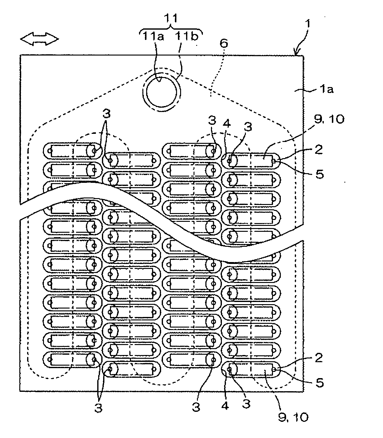
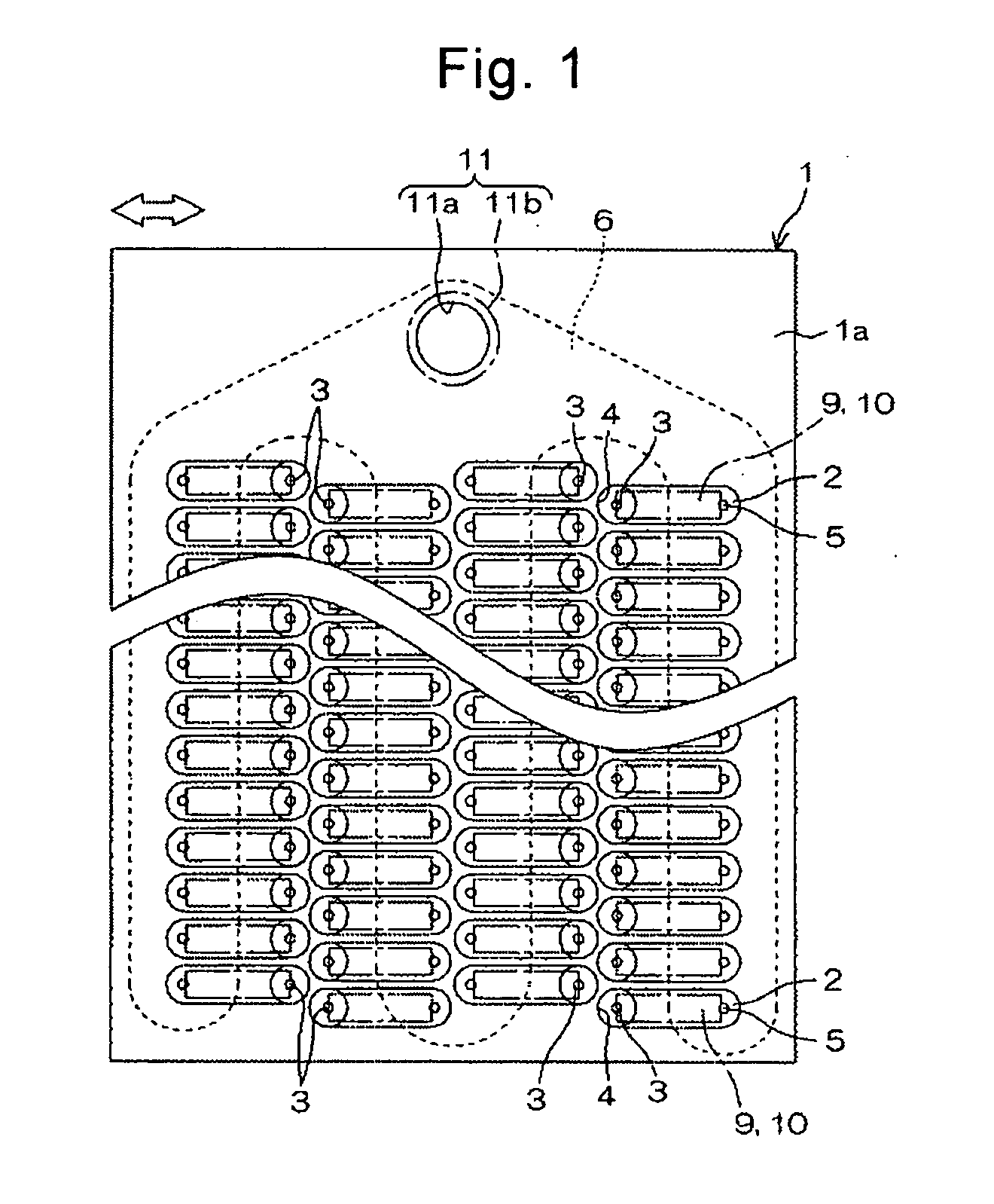
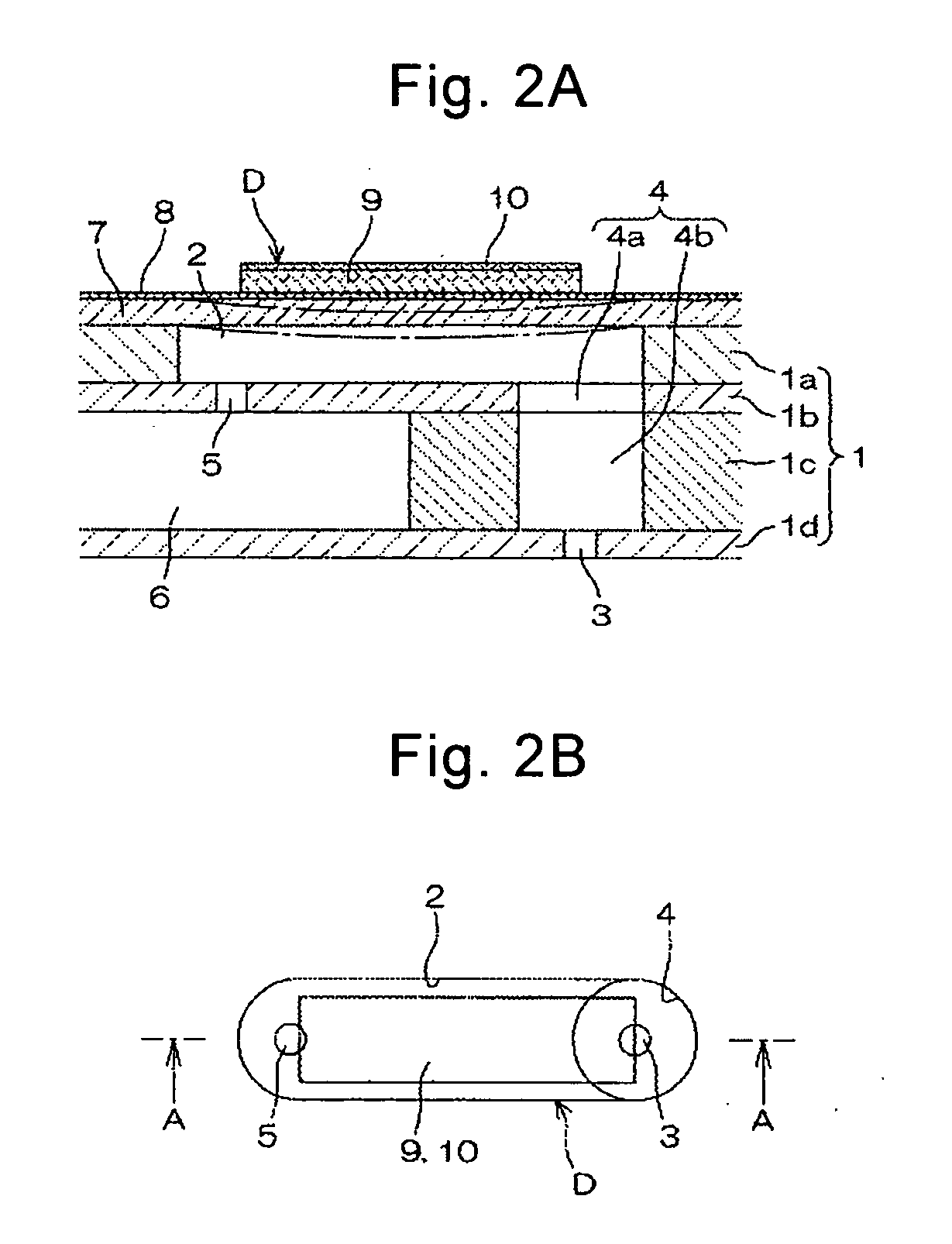
[0069] A piezoelectric inkjet head having the structure shown in FIG. 1 and FIGS. 2(a), (b), in which dot formation parts having the following structures are arranged on the substrate 1 was used.

[0070] pressure chamber 2: area 0.2 mm2, width 2200 μm, depth 100 μm

[0071] nozzle flow channel 4: diameter 200 μm, length 800 μm

[0072] supply port 5: diameter 30 μm, length 40 μm

[0073] nozzle 3: length 30 μm

[0074] opening 30: circle of 10 μm diameter

[0075] Each line includes 166 dot formation parts each consisting of the above parts, and in total (four lines), 664 dot formation parts are arranged on the substrate 1.

[0076] The pitch between the dot formation parts in the same line is 150 dpi, and the total of 600 dpi is established by shifting the neighboring lines by ½ pitch.

[0077] Next, a preparation example of pigment ink used in the present invention will be explained.

(Pigment Dispersion)

[0078] A pigment of commercially available copper ...


PUM


Abstract

An inkjet recording system that discharges pigment ink from a liquid droplet discharge head in which a part of wall surface of pressure chamber is formed of a piezoelectric element, wherein average surface inclination Δa (mrad) of surface of the piezoelectric element forming a part of wall surface of the pressure chamber satisfies Δa≦1050, and average volumetric particle diameter D (nm) of pigment contained in the ink satisfies 80≦D≦200. Preferably, the arithmetic average surface inclination Δa and the average volumetric particle diameter D of the pigment satisfy the following formula (1):
(1/D)×cos2a/1000)>0.003  (1).

Description

BACKGROUND OF THE INVENTION [0001] 1. Field of the Invention [0002] The present invention relates to an inkjet recording system realizing improved ink charging ratio (i.e., ratio between discharge nozzle number / total nozzle number) in discharging pigment ink through a liquid droplet discharge head, and providing excellent image quality. [0003] 2. Description of Related Art [0004] Conventionally, inkjet recording apparatuses serving as image forming apparatuses such as printer, facsimile machine, copying machine and plotter have been known. A liquid droplet discharge head used in such an inkjet recording apparatus includes a nozzle for discharging a liquid droplet, a liquid chamber (also referred to as discharge chamber, pressure chamber, pressurizing liquid chamber, ink flow channel) communicating with the nozzle, and an actuator that generates energy for pressurizing recording liquid (ink) in the liquid chamber, wherein a liquid droplet is discharged from the nozzle by causing pres...

Claims


Application Information

Patent Timeline
Patent Type & Authority Applications(United States)
IPC IPC(8): B41J2/045G01D11/00
CPCB41J2202/11B41J2/14233
Inventor OSANISHI, KATSUKI
Owner KYOCERA DOCUMENT SOLUTIONS INC
Why Eureka
Try Eureka