Dynamic word line drivers and decoders for memory arrays

a dynamic word line and memory array technology, applied in static storage, information storage, digital storage, etc., can solve the problems of increasing complexity and power consumption, placing a large electrical memory systems with a traditional dynamic/static circuit structure may place a heavy load on the clock, so as to reduce the timing delay from a clock to a particular wordline, the effect of increasing the capacitive noise-coupling immunity

Active Publication Date: 2008-04-10
QUALCOMM INC
View PDF13 Cites 14 Cited by
  • Summary
  • Abstract
  • Description
  • Claims
  • Application Information

AI Technical Summary

Benefits of technology

[0008]In another particular embodiment, an integrated circuit includes a substrate and a plurality of circuit devices. The circuit devices are arranged on the substrate to reduce capacitive coupling noise. The plurality of circuit devices includes a first wordline driver having a first pair of transistors and a first wordline output and includes a second wordline driver having a second pair of transistors and a second wordline output. The first and second wordline drivers are disposed on the substrate in a single row. A first wire trace couples the first pair of transistors to the first wordline output. The second wire trace couples the second pair of transistors to the second wordline output. The first wire trace and the second wire trace are substantially parallel. An advantage of this embodiment is that the layout provides increased capacitive noise-coupling immunity.
[0009]One particular advantage of a particular illustrative embodiment of the circuit device is that a timing delay from a clock to a particular wordline is reduced. Still another particular advantage of a particular illustrative embodiment of the circuit device is that the clock driver's capacitance loading may also be reduced. Another particular advantage of a particular illustrative embodiment is that use of multiple conditional clocks to selectively apply a clock signal reduces power consumption. In a particular embodiment, the clock power consumption may be reduced to one-fourth of the power consumed by a single clock system (e.g. the power consumption of a clock generator may be reduced by 75%). This reduction in power consumption provides an additional advantage in that power is conserved for use in other processes and / or to extend an operational life of a power source, such as a battery.
[0010]Still another particular advantage of a particular illustrative embodiment may be realized by sharing a common address signal among multiple wordline decoders, which reduces power consumption and conserves layout area. In a particular embodiment, four wordline drivers may share a common address signal, which reduces transistor gate loading of the decoders without decreasing speed.

Problems solved by technology

In general, memory systems with a traditional dynamic / static circuit structure may place a heavy load on the clock.
For example, in a memory structure having a plurality of wordline drivers, a single clock may drive multiple drivers and multiple address decoders, placing a large electrical load on the clock.
Additionally, each wordline driver may have its own decoded address input, which may place a large load on the decoder and which may utilize a large area of the circuit substrate, increasing complexity and power consumption.
Moreover, when the clock signal is provided to multiple wordline drivers, capacitive noise coupling between the wordline driver outputs may introduce additional design complexities.

Method used


Image

  • Dynamic word line drivers and decoders for memory arrays
  • Dynamic word line drivers and decoders for memory arrays
  • Dynamic word line drivers and decoders for memory arrays

Examples


Embodiment Construction

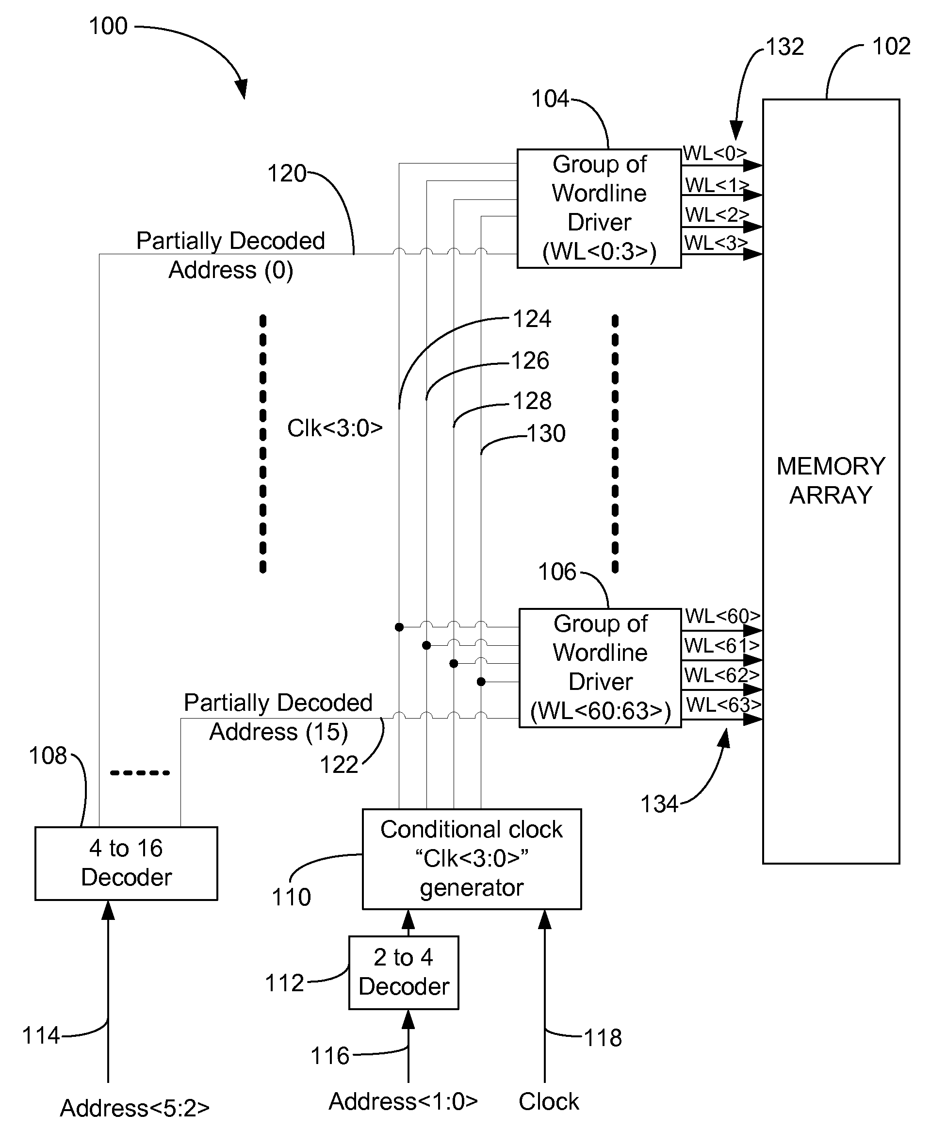
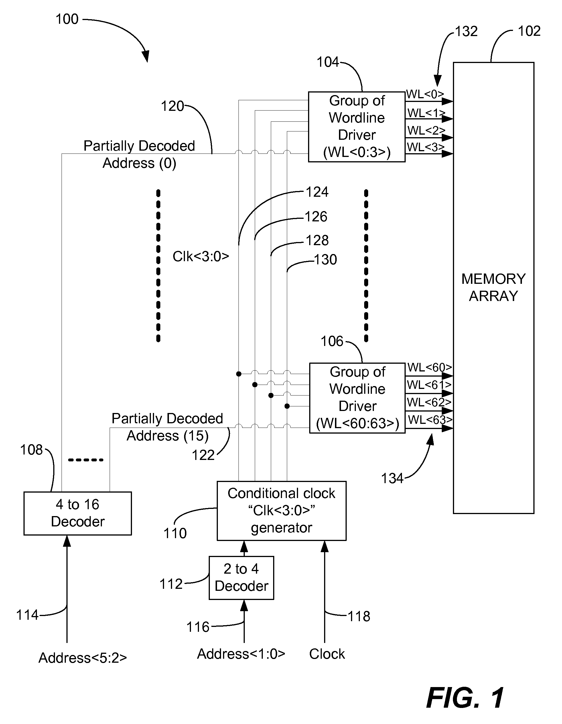
[0018]FIG. 1 is a block diagram of a particular illustrative embodiment of a wordline driver system 100 including a set of wordline drivers, such as the groups of wordline drivers 104 and 106 that are associated with a memory array 102. The system 100 may include multiple additional sets of wordline drivers (not shown). Each set of wordline drivers may control up to sixty-four wordlines (numbered zero to sixty-three) using sixty-four corresponding wordline drivers. The set of sixty-four wordlines and corresponding wordline drivers may be divided into groups of wordline drivers, such as the groups of wordline drivers 104 and 106. In a particular embodiment, the group of wordline drivers 104 may drive wordlines, such as the wordlines 132 from zero to three (WL, WL, WL, and WL), and the group of wordline drivers 106 may control wordlines, such as the wordlines 134 from sixty to sixty-three (WL, WL, WL, and WL). In this instance, each of the groups of wordline drivers 104 and 106 contro...


PUM


Abstract

In a particular illustrative embodiment, a circuit device that includes first logic and second logic is disclosed. The first logic receives a clock signal and a first portion of a memory address of a memory array, decodes the first portion of the memory address, and selectively applies the clock signal to a selected group of wordline drivers associated with the memory array. The second logic decodes a second portion of the memory address and selectively activates a particular wordline driver of the selected group of wordline drivers according to the second portion of the memory address.

Description

BACKGROUND[0001]I. Field[0002]The present disclosure generally relates to memory arrays, and more particularly, to dynamic wordline drivers and decoders for memory arrays.[0003]II. Description of Related Art[0004]In general, memory systems with a traditional dynamic / static circuit structure may place a heavy load on the clock. For example, in a memory structure having a plurality of wordline drivers, a single clock may drive multiple drivers and multiple address decoders, placing a large electrical load on the clock.[0005]Additionally, each wordline driver may have its own decoded address input, which may place a large load on the decoder and which may utilize a large area of the circuit substrate, increasing complexity and power consumption. Moreover, when the clock signal is provided to multiple wordline drivers, capacitive noise coupling between the wordline driver outputs may introduce additional design complexities. Hence, there is a need for improved wordline drivers.SUMMARY[0...

Claims


Application Information

Patent Timeline
Patent Type & Authority Applications(United States)
IPC IPC(8): G11C8/10G11C8/18G11C8/00
CPCG11C8/12G11C8/08G11C8/10
Inventor LIN, JENTSUNG
Owner QUALCOMM INC
Why Eureka
Try Eureka