Resin joined body

a technology of resin and body, applied in the field of resin joined body, can solve the problems of difficult to generate sufficient heat energy, heat developing on the rear side of the resin member, etc., and achieve the effects of suppressing the possibility, reducing light transmittance, and suppressing the deterioration of aesthetic appearan

Inactive Publication Date: 2008-04-10
NITTO DENKO CORP
View PDF9 Cites 6 Cited by
  • Summary
  • Abstract
  • Description
  • Claims
  • Application Information

AI Technical Summary

Benefits of technology

[0020]According to the present invention, the joined portion is formed in the fuse bonded portion so as to have the light transmittance (X(%)) of light which passes through the resin members via the fuse bonded portion being higher than the light transmittance (Y(%)) for the portion other than the fuse bonded portion (i.e., X>Y). Thus, it is possibl...

Problems solved by technology

However, this may pose a problem.
In addition, although not to such an extent as the absorbent does, the resin members themselves also absorb the laser beam to some extent, and therefore the increase in irradiation energy of the laser beam causes heat developing on this rear side of this resin member.
However, merely the use of the focused laser beam makes it difficult to generat...

Method used


Image

  • Resin joined body
  • Resin joined body
  • Resin joined body

Examples


example 1

[0056]A resin joined body of Example 1 was manufactured by using the following laser beam irradiation device.

(Laser Beam Irradiation Device Used in this Example)

[0057]Laser source: Semiconductor laser

[0058]Laser wavelength: 1490 nm

[0059]Maximum output: 15 W

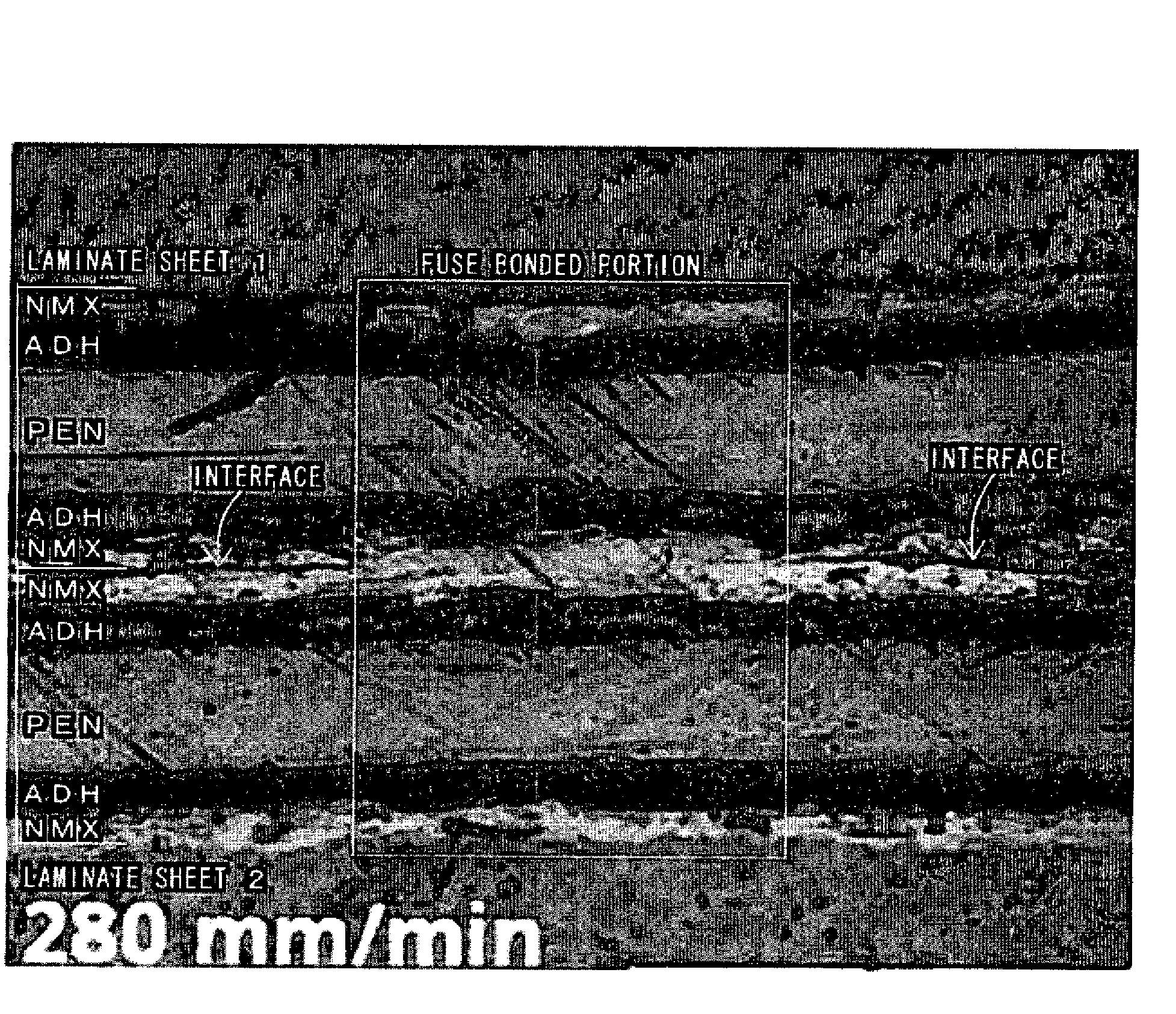
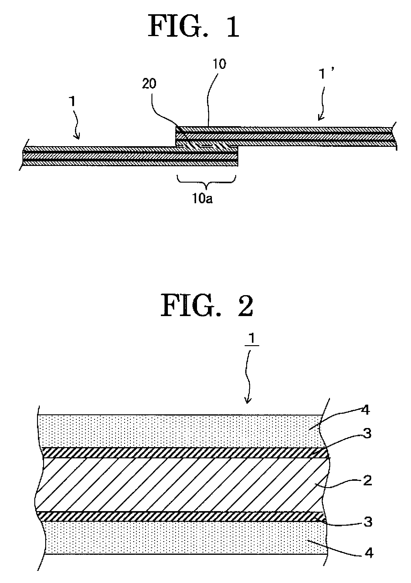
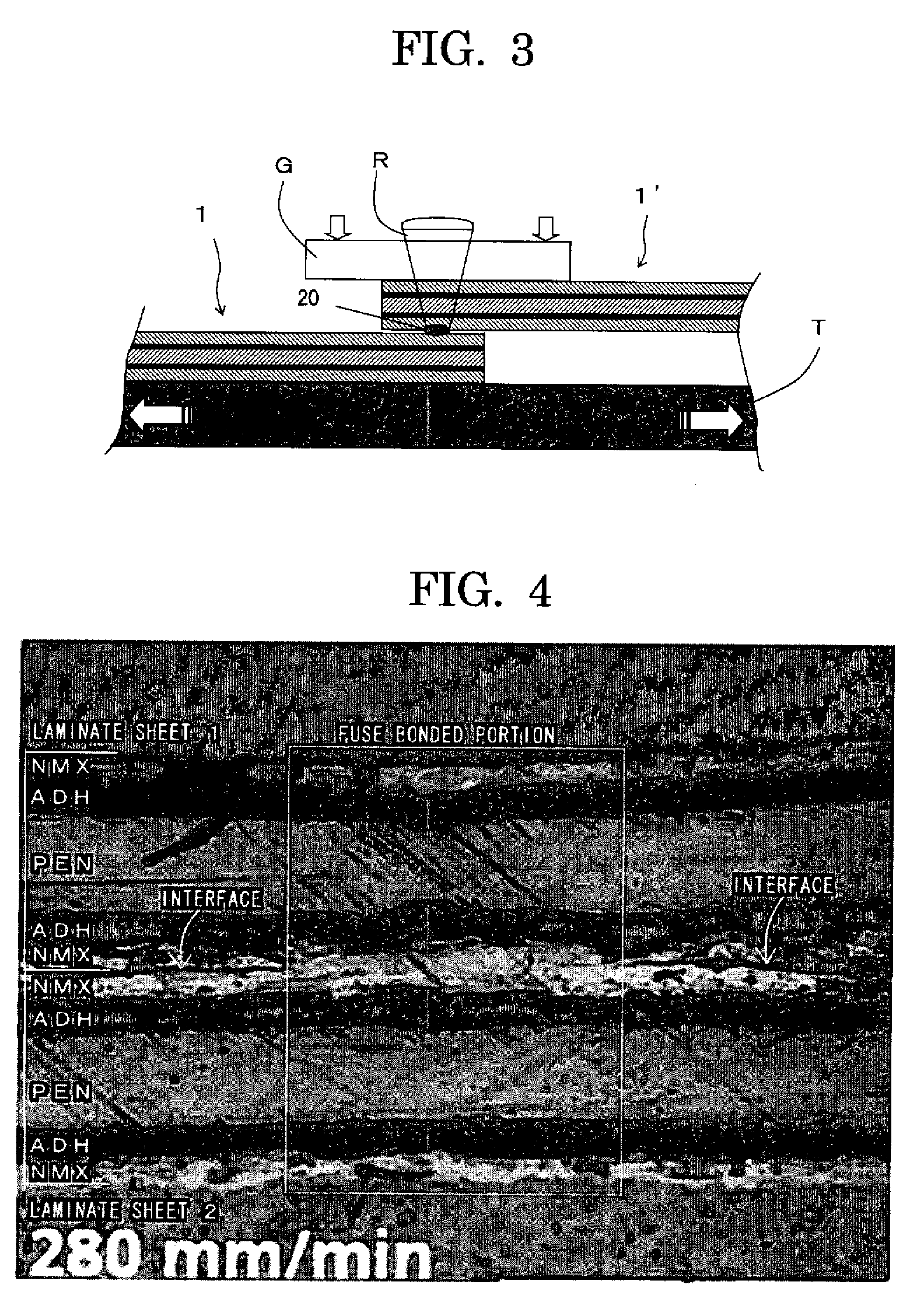
[0060]Two laminate sheets each having the following structure were used for manufacturing the resin joined body.

(Structure of a Laminate Sheet)

[0061]Five-layer structure of “aramid paper / adhesive / PEN film / adhesive / aramid paper”

[0062]The absorption constant of 1490 nm for the material and the thickness, of the respective layers was measured by using a spectrophotometer (trade name LAMBDA-9, manufactured by PerkinElemer). The results are shown below.

[0063]Aramid paper: (trade name NOMEXPAPER, manufactured by DuPont (thickness: 55 μm), absorption constant: 1081 m−1)

[0064]Adhesive: (acrylic adhesive (thickness: 30 μm), absorption constant: 360 m−1)

[0065]PEN film: (thickness: 125 μm, absorption constant: 94 m−1)

[0066]The absorption con...

example 2

[0072]A resin joined body was manufactured in the same manner as Example 1, except that the resin joined body was formed by laminate sheets each using an aramid paper having a thickness of 100 μm.

[0073]The shear strength of this resin joined body as measured was about 20 N (667 N / cm2), and it was found that an excellent joining strength was obtained.


PUM


Abstract

In a resin joined body including at least one member made of a resin material that forms a first resin layer and a second resin layer, the at least one of the first and second resin layers having the rear side from which the laser beam has been irradiated has an absorption constant of 50 to 5000 m−1 for the wavelength of the laser beam, and the fuse bonded portion is formed to have a relationship of X>Y, wherein a light transmittance of light passing from the first resin layer to the second resin layer via the fused portion is designated as X(%), and a light transmittance of light passing continuously from the first resin layer to the second resin layer via a portion other than the fused portion is designated as Y(%).

Description

CROSS REFERENCE TO RELATED APPLICATION[0001]This application claims priority from Japanese Patent Application No. 2006-274169, which is incorporated herein by reference.BACKGROUND OF THE INVENTION[0002]1. Field of the Invention[0003]The present invention relates to a resin joined body, and more particularly to a resin joined body formed by fuse bonding by using a laser beam.[0004]2. Discussion of the Background[0005]Conventionally, there are broadly known various methods of fuse bonding resin members together as a method of joining members together. Among these methods, many methods include overlapping resin members made of a resin material together with the overlapped resin members held in surface-to-surface contact with each other and irradiating a laser beam onto the overlapped portion to fuse the surfaces of the resin material, thereby forming a fuse bonded portion.[0006]For forming a resin joined body having the surfaces of the resin members fuse bonded together, infrared laser...

Claims


Application Information

Patent Timeline
IPC IPC(8): B32B27/34
CPCB29C65/1616B29C66/934B29C65/1654B29C65/8207B29C65/8253B29C66/1122B29C66/342B29C66/43B29C66/65B29C66/71B29C66/723B29C66/7292B29C66/81267B29C66/939B29C2035/0822B29K2105/0854B29K2277/10B29K2711/12B29K2909/08B29L2009/00B32B7/12B32B27/02B32B27/08B32B27/12B32B27/34B32B27/36B29C65/1635B29C66/9161B29C66/919B29C65/1638B29C66/8322B29C66/73921B29K2995/0027B29C66/8122B29C66/72328Y10T428/31504Y10T442/659Y10T428/31728B29K2077/10
Inventor MATSUO, NAOYUKIHINO, ATSUSHIKANETO, MASAYUKI
Owner NITTO DENKO CORP
Why Eureka
Try Eureka