
Automated, field-portable system for conducting toxicity measurements in water, soils, and sediments

a field-portable, automatic technology, applied in the direction of instruments, biomass after-treatment, specific use bioreactors/fermenters, etc., can solve the problems of requiring the skill of a laboratory technician, prone to user error, and complex current systems for determining the toxicity of soils, sediments, water,

Inactive Publication Date: 2008-04-10
THE GOVERNMENT OF THE UNITED STATES OF AMERICA AS REPRESENTED BY THE SEC OF THE NAVY NAVAL RES LAB WASHINGTON
View PDF1 Cites 6 Cited by
  • Summary
  • Abstract
  • Description
  • Claims
  • Application Information

AI Technical Summary

Benefits of technology

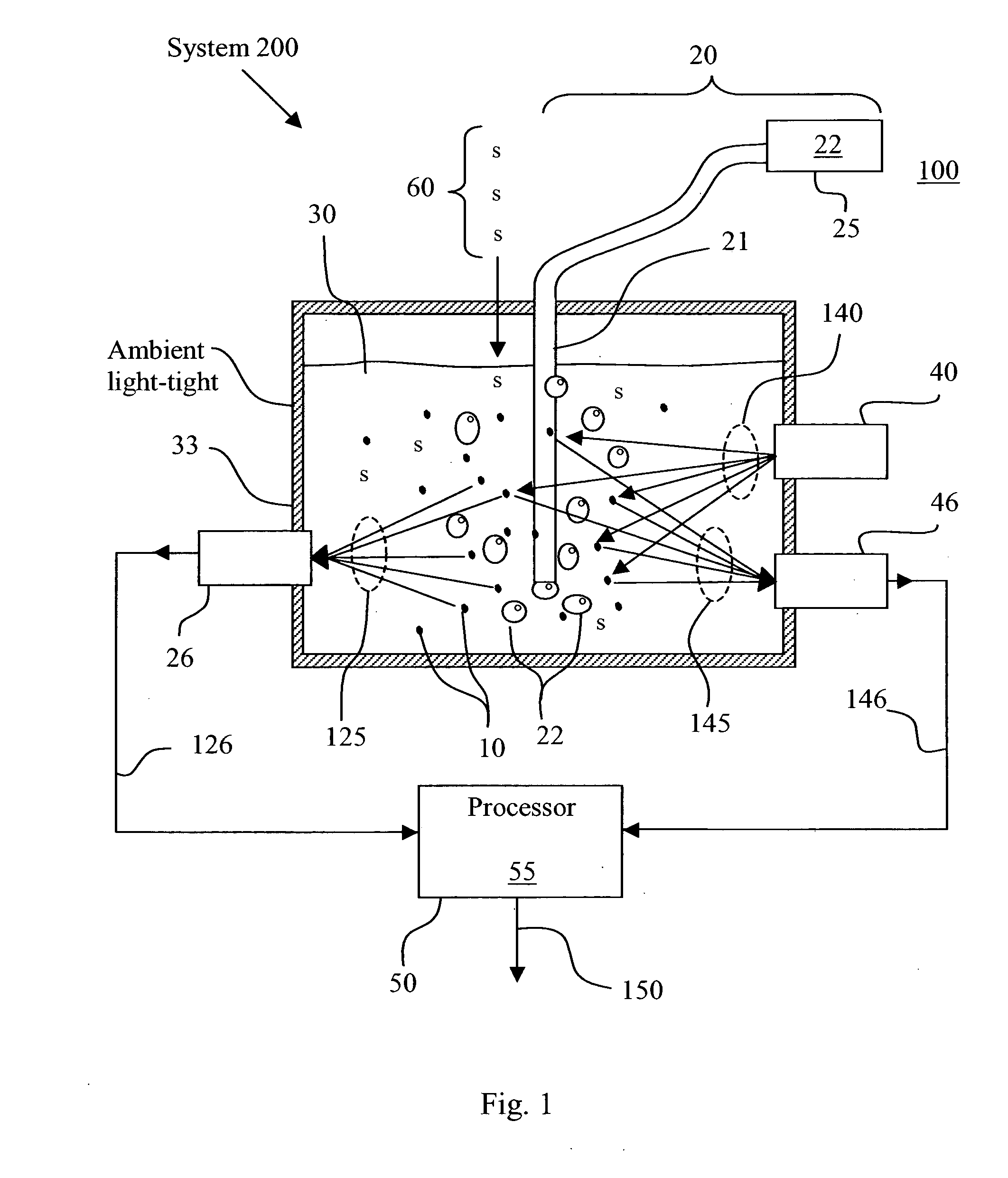
The patent text describes a system for testing the toxicity of water, soil, and sediments. The system is portable, easy to use, and can provide quick and accurate results. It uses live dinoflagellates to determine the toxicity levels of a sample. The system includes a test chamber with a transparent sample container and a red optical filter. It also has a distributor and a bar code scanner. The system is designed to be cost-effective and user-friendly. The technical effects of this patent are to provide a more efficient and reliable method for testing toxicity levels in environmental samples.

Problems solved by technology

Current systems for determining the toxicity of soils, sediments, and water tend to be complex, time consuming, and require the skill of a technician in a laboratory.
As a result, current toxicity tests can be expensive, and prone to user error.

Method used


Image

  • Automated, field-portable system for conducting toxicity measurements in water, soils, and sediments
  • Automated, field-portable system for conducting toxicity measurements in water, soils, and sediments
  • Automated, field-portable system for conducting toxicity measurements in water, soils, and sediments

Examples


Embodiment Construction

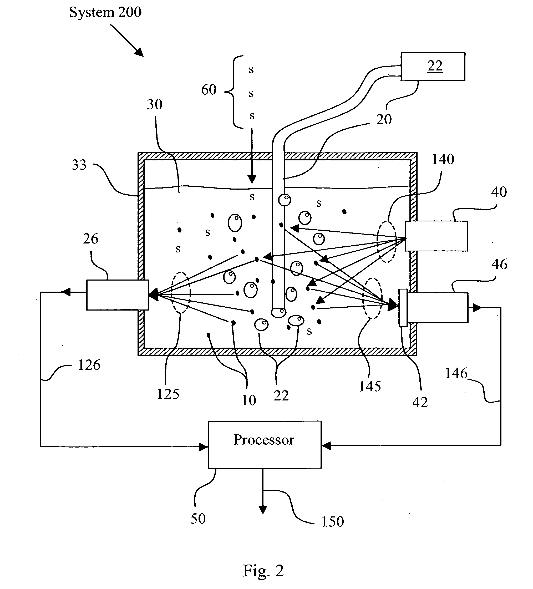
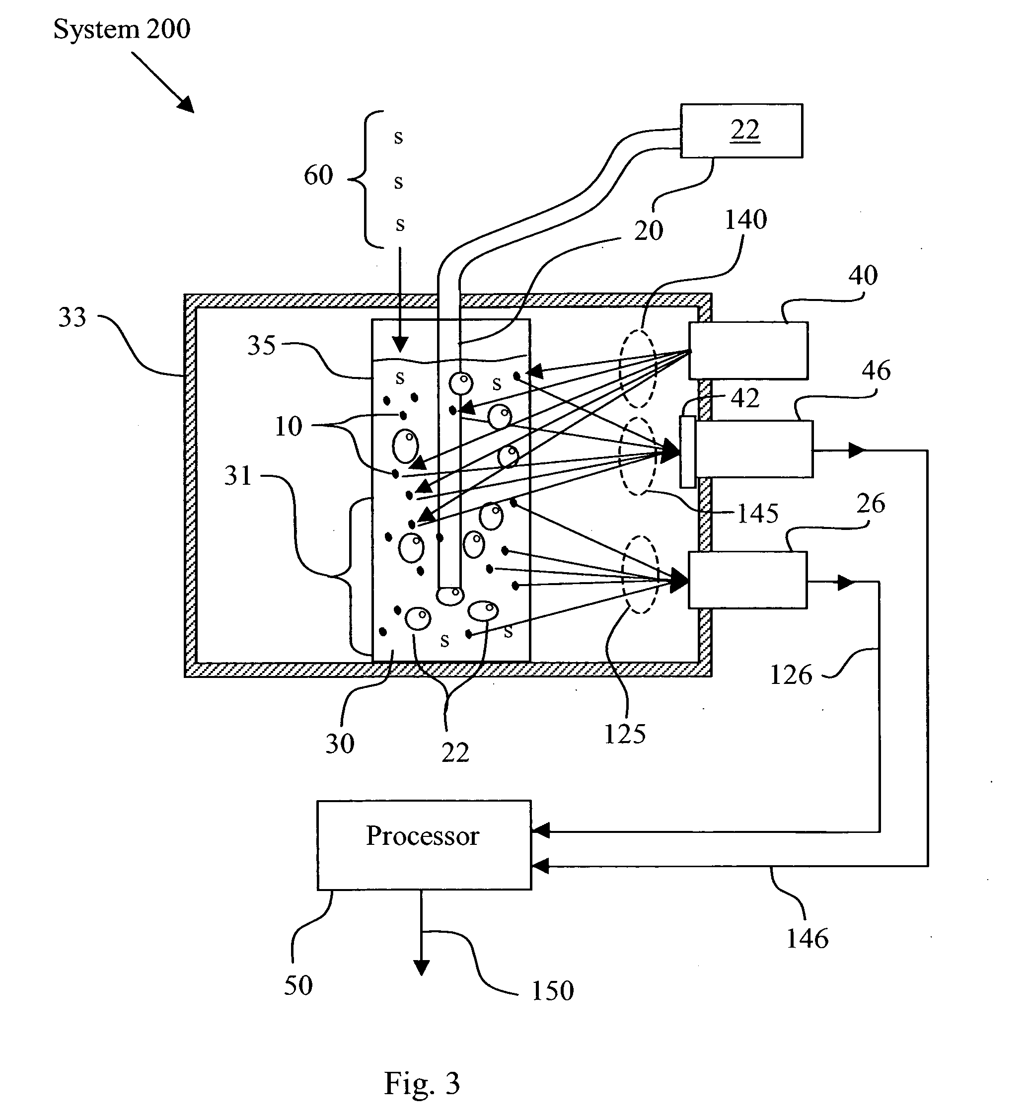
[0017]FIG. 1 shows a toxicity test system 200, a field-portable system for determining the toxicity of a test sample 60, such as water, soil and / or sediment. FIG. 1 shows how the test sample 60 may be added to an aqueous suspension 30 of dinoflagellates 10, which all may be contained in a test chamber 33. Inside the test chamber 33, if the dinoflagellates 10 are alive, the dinoflagellates 10 may be excited to fluoresce by an excitation signal 140 generated by an optical signal generator 40. The fluoresce signal 145 emitted by the excited dinoflagellates 10 may be detected by a first optical transducer 46 that is configured to produce a first data signal 146 in response to detecting the fluorescence signal 145. The first data signal 146 may be sent to a processor 50 where the first data signal 146 may be compared to control data 55. The dinoflagellates 10, inside the test chamber 33, may also be stimulated by a gas 22 to emit a bioluminescence signal 125 if the dinoflagellates 10 are...


PUM

PropertyMeasurementUnit
wavelengthaaaaaaaaaa

Abstract

A system for testing the toxicity of a test sample comprising: an aqueous suspension of dinoflagellates; a test chamber configured to contain the aqueous suspension of dinoflagellates and the test sample; an optical signal generator configured to emit an excitation signal for exciting the dinoflagellates to emit a fluorescence signal if the dinoflagellates are alive; a first optical transducer configured to produce a first data signal in response to detecting the fluorescence signal; a stimulator configured to introduce a gas into the aqueous suspension for stimulating the dinoflagellates to emit a bioluminescence signal if the dinoflagellates are alive; a second optical transducer configured to produce a second data signal in response to detecting the bioluminescence signal; and a processor configured to compare the first data signal and the second data signal to a control data to generate an output representing the toxicity of the test sample.

Description

CROSS-REFERENCE TO RELATED APPLICATIONS[0001]This application is a continuation in part of U.S. application Ser. No. 11 / 603,656, filed Nov. 22, 2006, entitled “Apparatus and Method for Providing Live Dinoflagellates for Toxicity Tests,” (Navy Case #98123), which is a continuation in part of both U.S. application Ser. No. 11 / 586,747, filed Oct. 10, 2006, entitled “Method for Stimulation of Bioluminescent Organisms Via Turbulence Created by Gas Bubbles” (Navy Case #98122); and U.S. application Ser. No. 11 / 586,745, filed Oct. 10, 2006, entitled “System and Method for Quantifying Toxicity in Water, Soil, and Sediments” (Parent Application 2) (Navy Case #98125). All of these applications are hereby incorporated by reference herein in their entirety for their teachings.FEDERALLY-SPONSORED RESEARCH AND DEVELOPMENT[0002]This invention was developed with federal funds and is assigned to the United States Government. Licensing and technical inquiries may be directed to the Office of Patent Co...

Claims


Application Information

Patent Timeline
Patent Type & Authority Applications(United States)
IPC IPC(8): C12Q1/00C12M3/00
CPCG01N21/6486G01N21/763G01N33/54366G01N33/5085G01N33/1866
Inventor BJORNDAL, BRYANLAPOTA, DAVID
Owner THE GOVERNMENT OF THE UNITED STATES OF AMERICA AS REPRESENTED BY THE SEC OF THE NAVY NAVAL RES LAB WASHINGTON
Learn More