Heat Exchanger

a heat exchanger and heat exchanger technology, applied in the field of heat exchangers, can solve the problems of increasing the number of brazing portions on the parts, affecting the heat exchange efficiency of the heat exchanger, and prone to leakage at the brazing portion, so as to enhance the heat exchange and prevent local boiling of cooling water.

Inactive Publication Date: 2008-04-17
T RAD CO LTD
View PDF32 Cites 25 Cited by
  • Summary
  • Abstract
  • Description
  • Claims
  • Application Information

AI Technical Summary

Benefits of technology

[0019] According to the present invention, inlet / outlet ports 11 are provided at the end portions of one side of the casing 9 via small tank portions 28, and a buffer plate 30 is provided in each of the small tank portions 28, thereby the first fluid 10 bypasses the buffer plate 30 to uniformly communicate into the individual portions in the first flow passage 3 to enhance the heat exchange. Since the inlet of the first flow passage 3 is formed to open in a slit shape narrower than the small tank portion 28, the velocity of the first fluid 10 entering through the opening increases. The kinetic energy of the first fluid 10 allows the first fluid 10 to reach a position distant from the lid member 9b. That is, the first fluid 10 enters the first flow passage 3 bypassing the buffer plate 30 and in a squeezed state.
[0020] With the above structure, when the plane of the tooth base 6c of the comb-state member 6 is in contact with the turned-up end edge 2 of the core body 5 at each end of the core body 5, and when the inlet of the first flow passage 3 is opened at the edge portion of the tooth base 6c at the root side of each comb tooth, a portion of the first fluid 10 bypassing the buffer plate 30 and entering the first flow passage 3 enters inside along the L-shape portion at the root of the comb tooth, and then is guided by the straight portion of each comb tooth to smoothly reach the edge portion in the width direction of the flat face of the first flow passage. Thereby the first fluid 10 uniformly communicates through the individual portions in the first flow passage 3 to enhance the heat exchange.
[0021] With the above structure, when the heat exchanger is used as the EGR cooler, the local boiling of cooling water can effectively be prevented.

Problems solved by technology

In the former heat exchanger such as the EGR cooler, the number of parts is large, which makes assembling cumbersome and increases the number of brazing portions on the parts, and there is a problem that a leakage tends to occur at the brazing portion.
The phenomenon leads to non-uniform flow of the first fluid in individual flow passages, which induces remaining of the first fluid at a portion of the flow passage.
Thus, the heat exchange at the stagnant fluid portion decreases to generate overheating portion, which is a defective phenomenon.

Method used


Image

  • Heat Exchanger
  • Heat Exchanger
  • Heat Exchanger

Examples


Embodiment Construction

[0029] Next, embodiments of the present invention will be described based on the attached drawings.

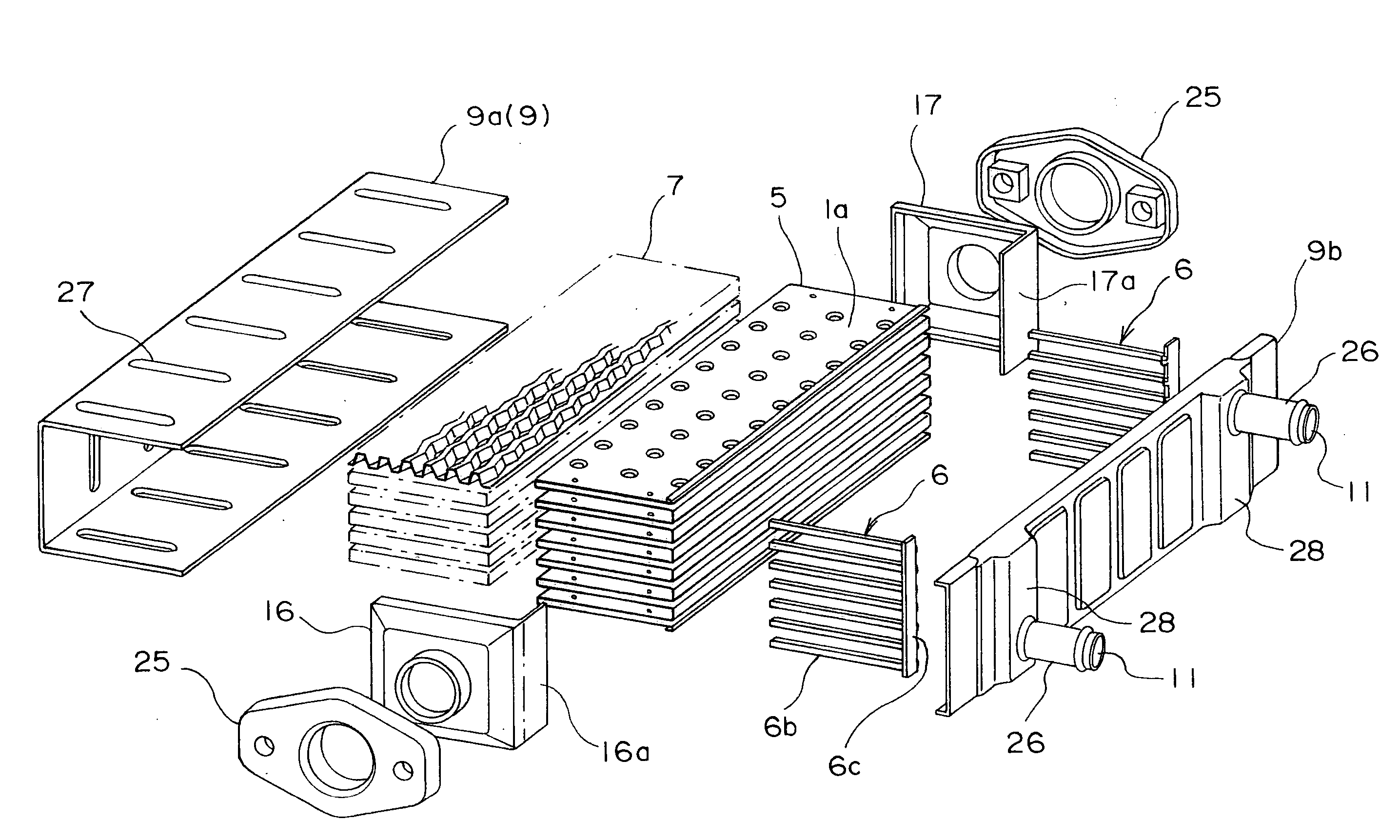
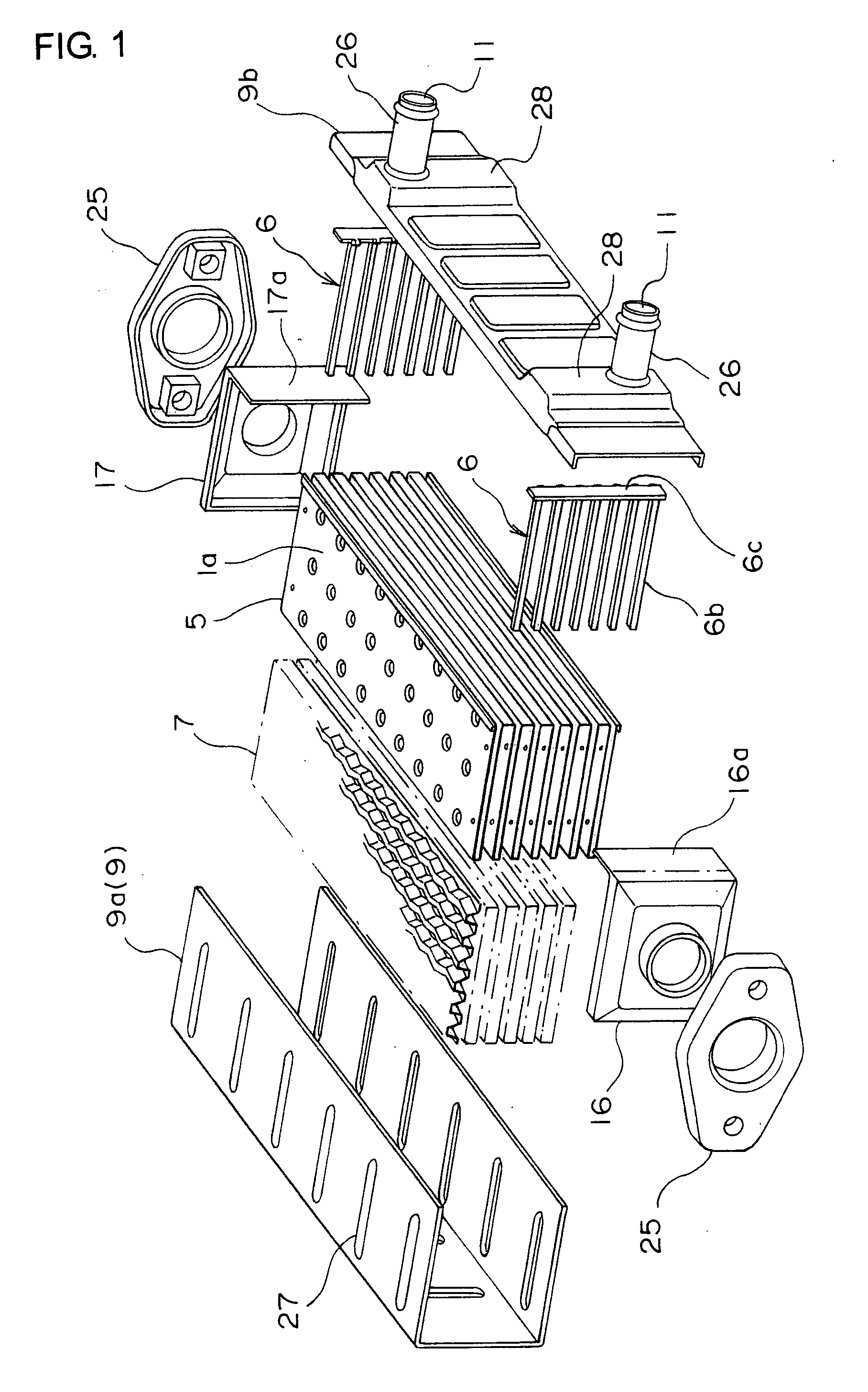
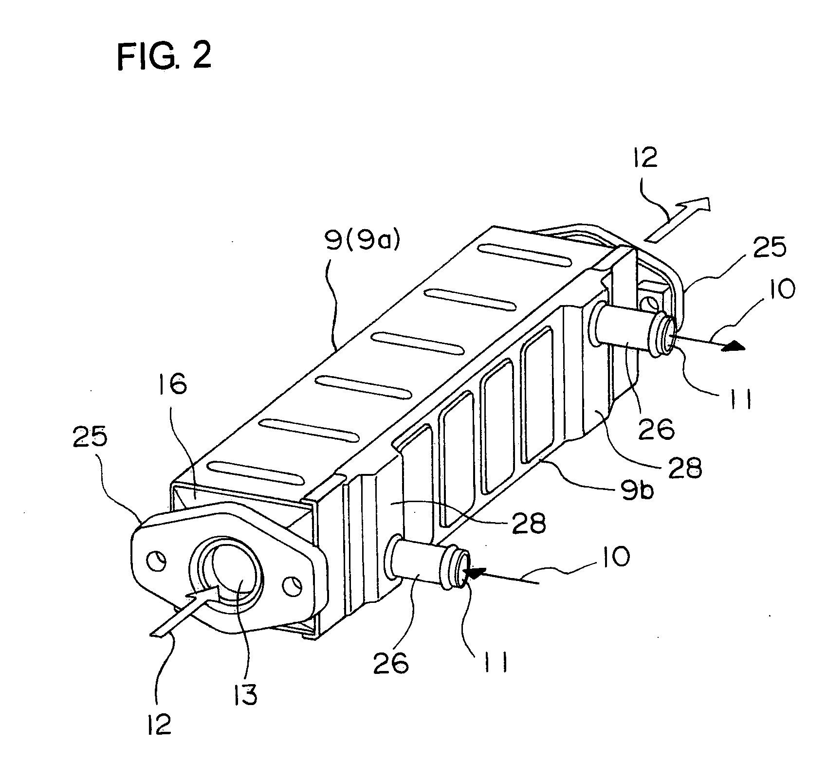
[0030]FIG. 1 is an exploded perspective view of a heat exchanger of the present invention, FIG. 2 shows its assembled state and FIG. 3 is an explanatory view of an assembly of a core body 5 and a comb-state member 6. Also, FIG. 4 is a perspective view of the comb-state member, FIG. 5 is a partially cutaway enlarged perspective view illustrating the assembled state, FIG. 6 is a perspective view of a principal part of the invention in a partially assembled state, and FIG. 7 is a principal part longitudinal cross sectional view of the invention.

[0031] This heat exchanger has a core body 5, a large number of fins 7, a casing 9, a pair of headers 16, 17, and the pair of comb-state members 6.

[0032] The core body 5 is formed by turning up and bending a strip-shaped metal plate in a fanfold manner as shown in FIG. 3 so that turned-up end edges 1, 2 are formed alternately at one end and the ...


PUM


Abstract

This invention is structured by: forming a core body by turning-up a strip-shaped metal plate in fanfold manner to create a large number of flat flow passages; blocking the individual flow passages at both ends thereof using the respective comb teeth of a pair of comb-state members; and fitting the casing to the core body, while providing inlet/outlet port of the fluid at a side face of the casing. The object of the invention is to establish uniform communication of the fluid in individual flat flow passages. As a means for achieving the object, a pair of header portions are provided at both end portions of the cylindrical casing, the inlet/outlet ports are provided at both edge portions of one side of the casing via a pair of small tank portions, the small tank portion at inlet side of the first fluid has a buffer plate arranged at a position closer to the outlet side of the first fluid between the core body and the inlet/outlet port, thereby allowing the first fluid to bypass the buffer plate in the small tank portion and to enter an end portion of the first flow passage from an edge opposite to the outlet.

Description

BACKGROUND OF THE INVENTION [0001] The present invention relates to a heat exchanger in a simple structure which can be applied to a heat exchanger (EGR cooler) used in an exhaust gas recirculation apparatus in an automobile and other heat exchangers, in which a core body formed by bending a strip-shaped metal plate in a fanfold manner, and having flat first flow passages and second flow passages alternately in the thickness direction of the metal plate, each of the first flow passages of the core body being blocked by each tooth of a pair of comb-state members at both end positions. [0002] A conventional EGR cooler is made of an assembly of a large number of flat tubes or a large number of plates, a large number of fins, a casing and a header, in which cooling water is made to communicate through the casing side and an exhaust gas is made to communicate inside each of the flat tubes or the like as proposed in the invention described in Japanese Patent Application Laid-Open No. 5-18...

Claims


Application Information

Patent Timeline
Patent Type & Authority Applications(United States)
IPC IPC(8): F28D7/10
CPCF02M25/0737F28D9/0025Y02T10/121F28F9/026F28F2220/00F28F3/025F28F21/083F02M26/32
Inventor NAKAMURA, YOICHI
Owner T RAD CO LTD
Why Eureka
Try Eureka