Optimized well spacing for in situ shale oil development

a well spacing and in situ technology, applied in the direction of well accessories, earthwork drilling and mining, fluid removal, etc., can solve the problems of limited application to very shallow formations, decomposition of kerogen, and limited application of shale oil development to achieve the effect of reducing the secondary cracking of hydrocarbons

Inactive Publication Date: 2008-04-17
KAMINSKY ROBERT D +1
View PDF81 Cites 61 Cited by
  • Summary
  • Abstract
  • Description
  • Claims
  • Application Information

AI Technical Summary

Benefits of technology

[0030]The present inventions also include a method for arranging heater wells for an in situ kerogen conversion process. In one aspect, the method includes providing a production well, and completing a plurality of heater wells around the production well such that the plurality of heater wells comprise a first layer of heater wells around the production well, and then a second layer of heater wells around the first layer. In this method, the heater wells in the second layer of wells are arranged relative to the heater wells in the first layer of wells so as to minimize secondary cracking of hydrocarbons converted from the kerogen as the hydrocarbons flow from the second layer of wells to the production well. The first and second layers may optionally comprise heater wells that are elongated in a direction in which thermal energy travels most efficiently through a targeted subsurface formation.

Problems solved by technology

Kerogen is subject to decomposing upon exposure to heat over a period of time.
However, the practice has been mostly discontinued in recent years because it proved to be uneconomical or because of environmental constraints on spent shale disposal.
Further, surface retorting requires mining of the oil shale, which limits application to very shallow formations.
While research projects have been conducted in this area from time to time, no serious commercial development has been undertaken.

Method used


Image

  • Optimized well spacing for in situ shale oil development
  • Optimized well spacing for in situ shale oil development
  • Optimized well spacing for in situ shale oil development

Examples


Embodiment Construction

Definitions

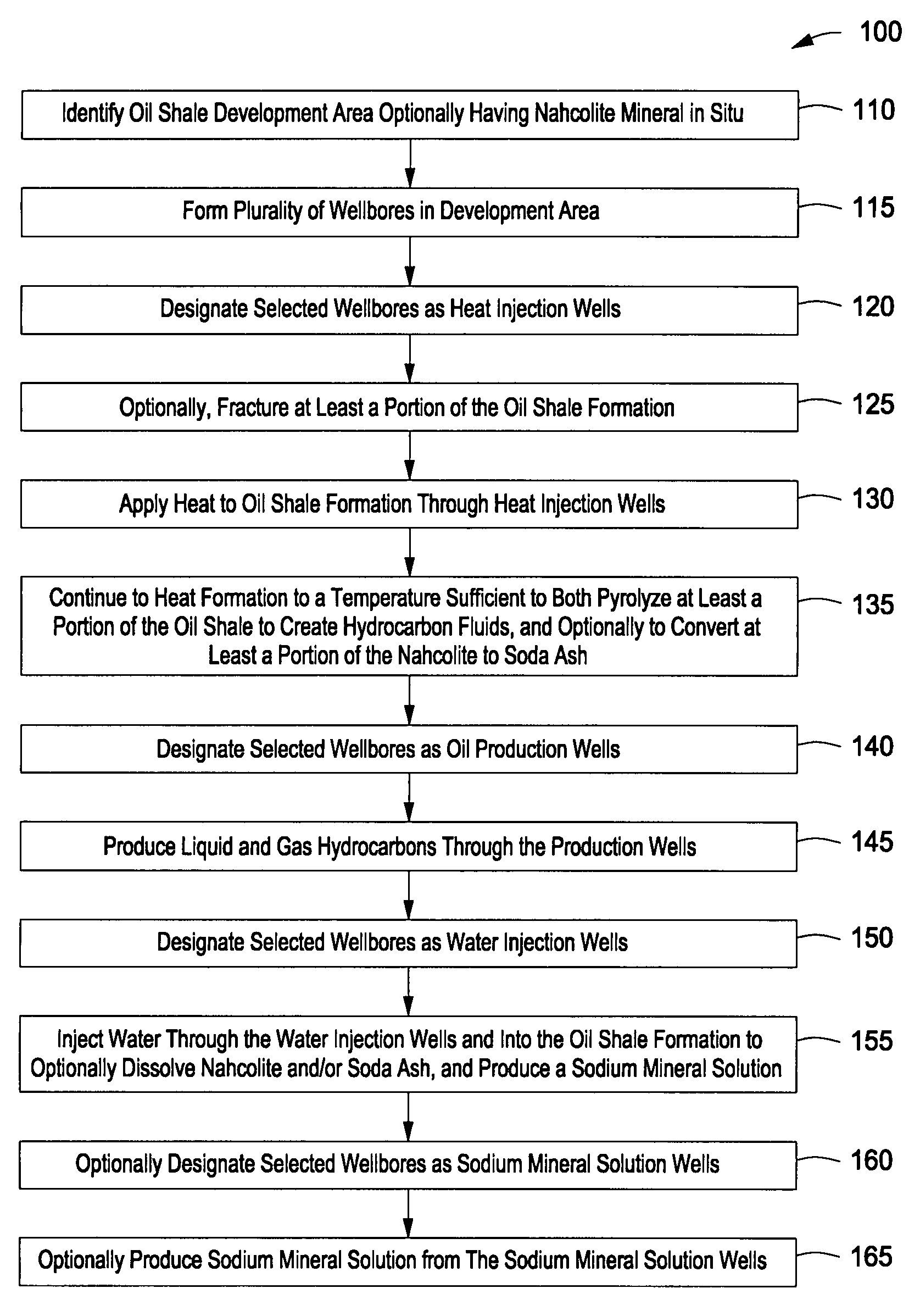
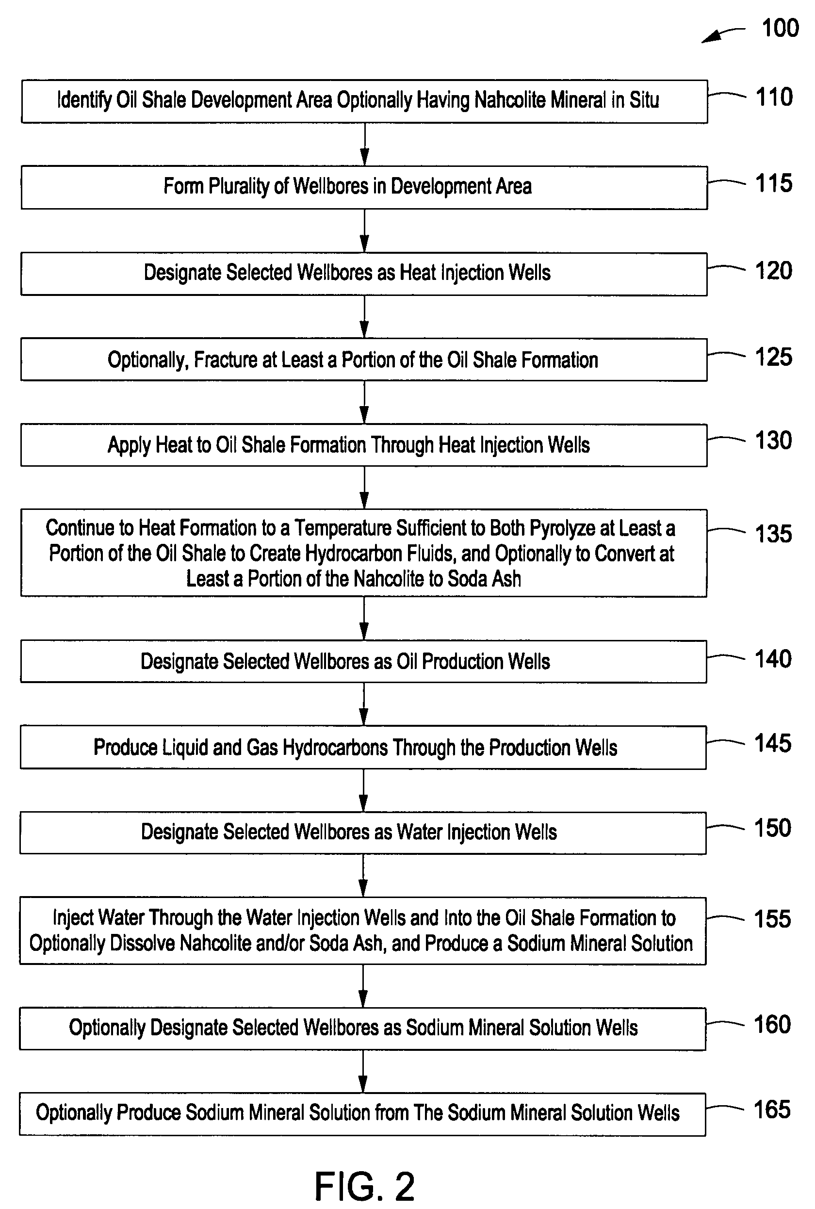
[0044]As used herein, the term “hydrocarbon(s)” refers to organic material with molecular structures containing carbon bonded to hydrogen. Hydrocarbons may also include other elements, such as, but not limited to, halogens, metallic elements, nitrogen, oxygen, and / or sulfur.

[0045]As used herein, the term “hydrocarbon fluids” refers to a hydrocarbon or mixtures of hydrocarbons that are gases or liquids. For example, hydrocarbon fluids may include a hydrocarbon or mixtures of hydrocarbons that are gases or liquids at formation conditions, at processing conditions or at ambient conditions (15° C. and 1 atm pressure). Hydrocarbon fluids may include, for example, oil, natural gas, coalbed methane, shale oil, pyrolysis oil, pyrolysis gas, a pyrolysis product of coal, and other hydrocarbons that are in a gaseous or liquid state.

[0046]As used herein, the terms “produced fluids” and “production fluids” refer to liquids and / or gases removed from a subsurface formation, including, f...


PUM


Abstract

A method for spacing heater wells for an in situ conversion process is provided. The method includes the steps of determining a direction along which thermal energy will travel most efficiently through a subsurface formation, and completing a plurality of heater wells in the subsurface formation, with the heater wells being spaced farther apart in the determined direction than in a direction transverse to the determined direction. In one aspect, the step of determining a direction along which thermal energy will travel most efficiently is performed based upon a review of geological data pertaining to the subsurface formation. The geological data may comprise the direction of least horizontal principal stress in the subsurface formation. Alternatively, the geological data may comprise the direction of bedding in the subsurface formation, the tilt of the subsurface formation relative to the surface topography, the organic carbon content of the kerogen, the initial formation permeability, and other factors.

Description

STATEMENT OF RELATED APPLICATIONS[0001]This application claims the benefit of U.S. Provisional application 60 / 851,541 which was filed on Oct. 13, 2006. The provisional application is incorporated herein in its entirety by reference.BACKGROUND OF THE INVENTION[0002]1. Field of the Invention[0003]The present invention relates to the field of hydrocarbon recovery from subsurface formations. More specifically, the present invention relates to the in situ recovery of hydrocarbon fluids from organic-rich rock formations, including, for example, oil shale formations, coal formations and tar sands formations. The present invention also relates to the arrangement of wellbores in a shale oil development area.[0004]2. Background of the Invention[0005]Certain geological formations are known to contain an organic matter known as “kerogen.” Kerogen is a solid, carbonaceous material. When kerogen is imbedded in rock formations, the mixture is referred to as oil shale. This is true whether or not t...

Claims


Application Information

Patent Timeline
Patent Type & Authority Applications(United States)
IPC IPC(8): E21B43/30
CPCE21B41/0064Y02C10/14E21B43/30E21B43/243Y02C20/40
Inventor KAMINSKY, ROBERT D.SYMINGTON, WILLIAM A.
Owner KAMINSKY ROBERT D
Why Eureka
Try Eureka