AC-coupled differential drive circuit for opto-electronic modulators

a technology of optoelectronic modulators and differential drives, which is applied in the direction of electric/magnetic computing, instruments, and computations using denominational number representations, etc., can solve the problems of direct impact on the capacitor structure of phase-shifting elements, the dynamic behavior of the laser itself introduces distortion, and the use of lithium niobate-based optical devices in such situations is not an option, so as to extend the available bandwidth of the modulator

Active Publication Date: 2008-04-17
CISCO TECH INC
View PDF19 Cites 16 Cited by
  • Summary
  • Abstract
  • Description
  • Claims
  • Application Information

AI Technical Summary

Benefits of technology

[0009] In accordance with the present invention, an AC-coupled differential drive circuit for an optical modulator is utilized, where a common “node” is defined between top (or bottom) plates of the modulator arms themselves (as described above, the “arms” of an SOI-based modulator take the form of MOS capacitors). A low pass filter is disposed between the differential driver output and the modulator to provide the desired AC coupling by filtering out the DC bias voltage of the driver circuit itself. A...

Problems solved by technology

The disadvantage of this method is that when higher switching speeds are required, the dynamic behavior of the semiconductor material of the laser itself introduces distortion, primarily in the form of chirp.
Clearly, the use of lithium niobat...

Method used


Image

  • AC-coupled differential drive circuit for opto-electronic modulators
  • AC-coupled differential drive circuit for opto-electronic modulators
  • AC-coupled differential drive circuit for opto-electronic modulators

Examples


Embodiment Construction

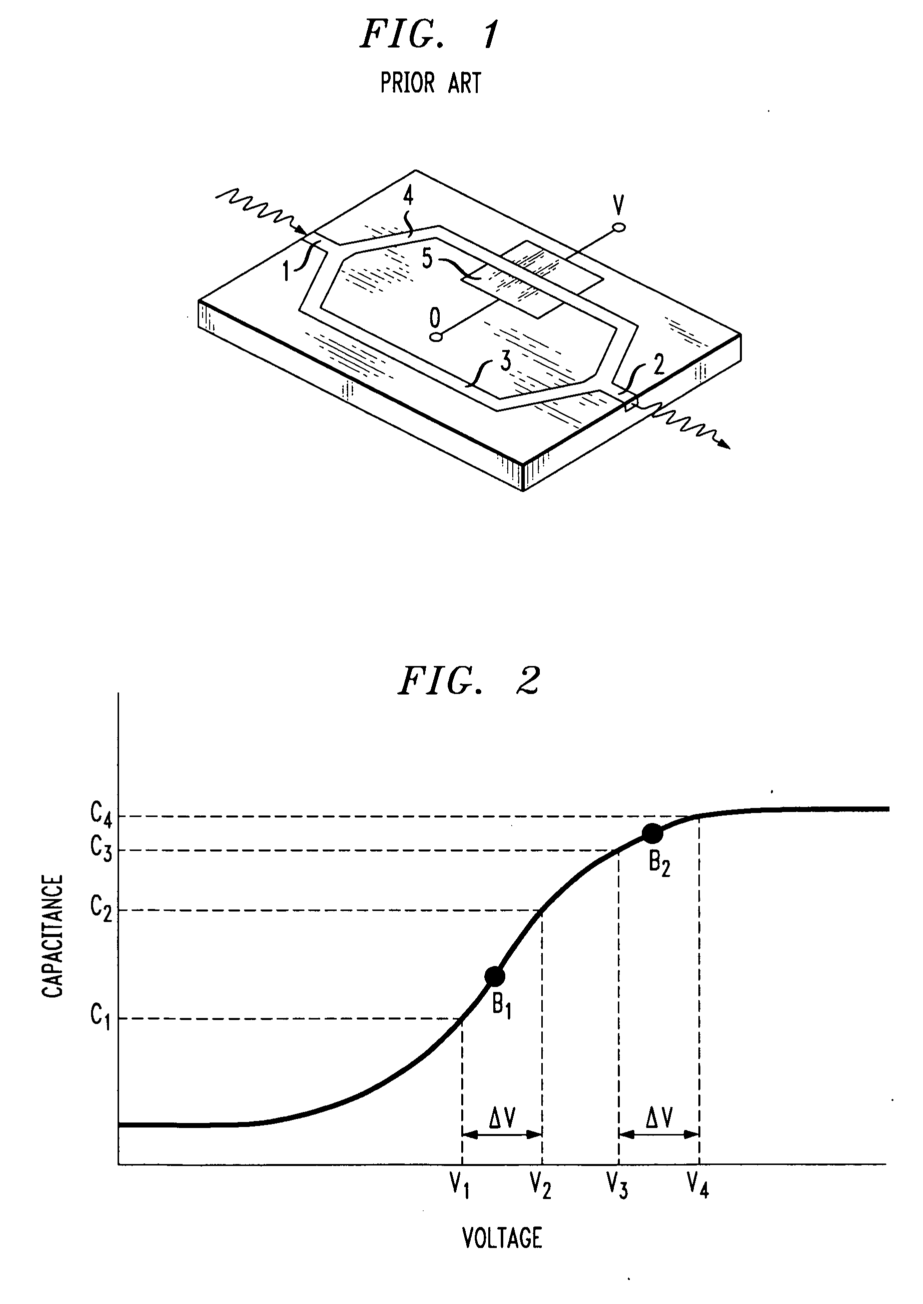
[0017]FIG. 1 illustrates an exemplary Mach-Zehnder modulator that may be configured to utilize the AC-coupled differential drive arrangement of the present invention. As shown, the modulator comprises an input waveguide section 1 and an output waveguide section 2. A pair of modulator arms 3 and 4 are shown, where each arm is formed to include a capacitor-like structure. U.S. Pat. Nos. 6,845,198 and 7,065,301 and incorporated herein by reference, describe the formation details of such modulators.

[0018] In operation, an incoming continuous wave (CW) light signal from a laser source (not shown) is coupled into input waveguide section 1. The CW signal is coupled into waveguide arms 3 and 4, wherein the application of the electrical drive signal to these arms will provide the desired phase shift to modulate the optical signal, forming a modulated optical output signal along output waveguide 2. A pair of electrodes 5 are illustrated in association with modulator arm 4, where a similar pa...


PUM


Abstract

An AC-coupled differential drive circuit for an optical modulator is utilized, where a common “node” is defined between top (or bottom) plates of the modulator arms themselves (the “arms” of a modulator taking the form of MOS capacitors). A low pass filter is disposed between the differential driver output and the modulator's common node to provide the desired AC coupling by filtering out the DC bias voltage of the driver circuit itself without the need for a separate, external AC coupling capacitor. An independent, adjustable DC potential can then be applied to the common node, and will appear in a balanced manner across each arm of the modulator to provide the desired DC bias for the modulator independent of the DC bias of the driver circuit.

Description

CROSS-REFERENCE TO RELATED APPLICATION [0001] This application claims the benefit of U.S. Provisional Application No. 60 / 849,893, filed Oct. 7, 2006.TECHNICAL FIELD [0002] The present invention relates to an electrical driver circuit for an opto-electronic modulator and, more particularly, to an AC-coupled differential driver that allows for the bias point of the modulator to be adjusted independently of the voltage swing of the electrical drive signal. BACKGROUND OF THE INVENTION [0003] Optical transmission systems are generally based on one of two methods of modulation of an optical signal, either direct modulation or external modulation. In the first of these methods, the bias current applied to a laser is modulated, turning the laser “on” and “off”. The disadvantage of this method is that when higher switching speeds are required, the dynamic behavior of the semiconductor material of the laser itself introduces distortion, primarily in the form of chirp. External modulation of a...

Claims


Application Information

Patent Timeline
IPC IPC(8): G06G7/14
CPCG02F2001/212G02F1/2255G02F1/212
Inventor MOSINSKIS, PAULIUS
Owner CISCO TECH INC
Why Eureka
Try Eureka