Method and system for power line networking for industrial process control applications

a technology for industrial process control and power line network, applied in the direction of electric controllers, instruments, ignition automatic control, etc., can solve the problems of interference with conventional data signals, which are often unshielded, and achieve the effect of selective connection and easy implementation

Inactive Publication Date: 2008-04-17
ASOKA USA CORP
View PDF17 Cites 4 Cited by
  • Summary
  • Abstract
  • Description
  • Claims
  • Application Information

AI Technical Summary

Benefits of technology

[0009] In a specific embodiment, the present invention includes a real-time management networking system for a manufacturing environment, e.g., chemical, assembly, automobile, electronic, petroleum. In a specific embodiment, the system has a spatial region, which is adapted for one or more manufacturing equipment devices. The one or more manufacturing equipment devices is associated with a manufacture of a product. In a specific embodiment, the manufacturing equipment is able to generate a high frequency noise, which causes interference with a conventional data signal, which is often unshielded. In a specific embodiment, the system has a power line gateway device provided within a desired region of the spatial region. The power line gateway device has a power line device coupled to an interface device and a coupling device. In a specific embodiment, the interface device is coupled to a data connection. The power line device is capable of converting a data signal from the data connection into a power line signal. In a preferred embodiment, the system also has one or more shielded ca

Problems solved by technology

In a specific embodiment, the manufacturing equipment is able to generate a high frequency

Method used


Image

  • Method and system for power line networking for industrial process control applications
  • Method and system for power line networking for industrial process control applications
  • Method and system for power line networking for industrial process control applications

Examples


Embodiment Construction

[0020] According to the present invention, techniques for power line networking techniques for industrial applications are provided. More particularly, the invention provides a method and system for a high speed power line network in an industrial environment such as manufacturing of electronic devices, mechanical devices, chemical / petrochemical, and petroleum products. Merely by way of example, the invention has been applied in a local area network environment, but it would be recognized that other applications exist.

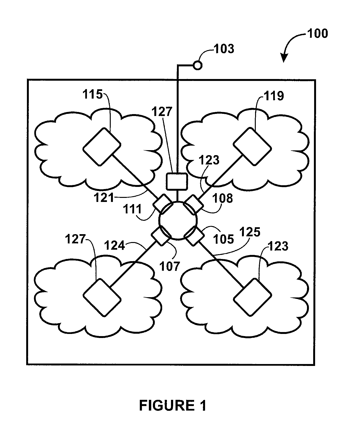
[0021]FIG. 1 is a simplified diagram of a real-time management networking system 100 according to an embodiment of the present invention. This diagram is merely an example, which should not unduly limit the scope of the claims herein. One of ordinary skill in the art would recognize many variations, alternatives, and modifications. As shown, the diagram illustrates a real-time management networking system for a manufacturing environment. In a specific embodiment, the ...


PUM


Abstract

A real-time management networking system for a manufacturing environment, e.g., chemical, assembly, automobile, electronic, petroleum. In a specific embodiment, the system has a spatial region, which is adapted for one or more manufacturing equipment devices. The one or more manufacturing equipment devices is associated with a manufacture of a product. In a specific embodiment, the manufacturing equipment is able to generate a high frequency noise, which causes interference with a conventional data signal, which is often unshielded. In a specific embodiment, the system has a power line gateway device provided within a desired region of the spatial region. The power line gateway device has a power line device coupled to an interface device and a coupling device. In a specific embodiment, the interface device is coupled to a data connection. The power line device is capable of converting a data signal from the data connection into a power line signal. In a preferred embodiment, the system also has one or more shielded cables coupled to the coupling device and an outlet device coupled to at least the one or more shielded cables. In a preferred embodiment, the outlet device is adapted to convert the power line signal into at least an Ethernet signal or a RS232 signal. In preferred embodiments, the Ethernet signal or RS232 signal is substantially free from interference from the high frequency noise.

Description

CROSS-REFERENCES TO RELATED APPLICATIONS [0001] This application claims priority to U.S. Provisional Application No. 60 / 824,227, filed Aug. 31, 2006, which is related to U.S. patent application Ser. No. 11 / 245,700, filed Oct. 7, 2005. Both applications are commonly assigned, and hereby incorporated by reference for all purposes.BACKGROUND OF THE INVENTION [0002] The present invention relates generally to power line networking techniques for industrial applications. More particularly, the invention provides a method and system for a high speed power line network in an industrial environment such as manufacturing of electronic devices, mechanical devices, chemical / petrochemical, and petroleum products. Merely by way of example, the invention has been applied in a local area network environment, but it would be recognized that other applications exist. [0003] Telecommunication techniques have been around for numerous years. In the early days, a communication technique known as telegrap...

Claims


Application Information

Patent Timeline
IPC IPC(8): G05B11/01
CPCH04B3/542H04B2203/5487H04B2203/5475H04B2203/5466
Inventor CHAN, TAT KEUNG
Owner ASOKA USA CORP
Why Eureka
Try Eureka