Knock determining device and method for internal combustion engine

a technology of determining device and internal combustion engine, which is applied in the direction of electric/magnetic computing, analogue processes for specific applications, instruments, etc., can solve the problems of difficult to accurately distinguish the knocking from the noise, and the noise and knocking may not be accurately distinguished

Inactive Publication Date: 2008-04-17
DENSO CORP +2
View PDF8 Cites 14 Cited by
  • Summary
  • Abstract
  • Description
  • Claims
  • Application Information

AI Technical Summary

Problems solved by technology

However, since the driving noise of the fuel injection valve of cylinder injection engine, and the driving noise of the variable valve timing device are increasing, it is difficult to distinguish the knocking from the noise accurately.
Thus, when the vibration waveform of the noise ...

Method used


Image

  • Knock determining device and method for internal combustion engine
  • Knock determining device and method for internal combustion engine
  • Knock determining device and method for internal combustion engine

Examples


first embodiment

[0016]Referring to FIGS. 1 to 3, a first embodiment of the present invention will be described hereinafter.

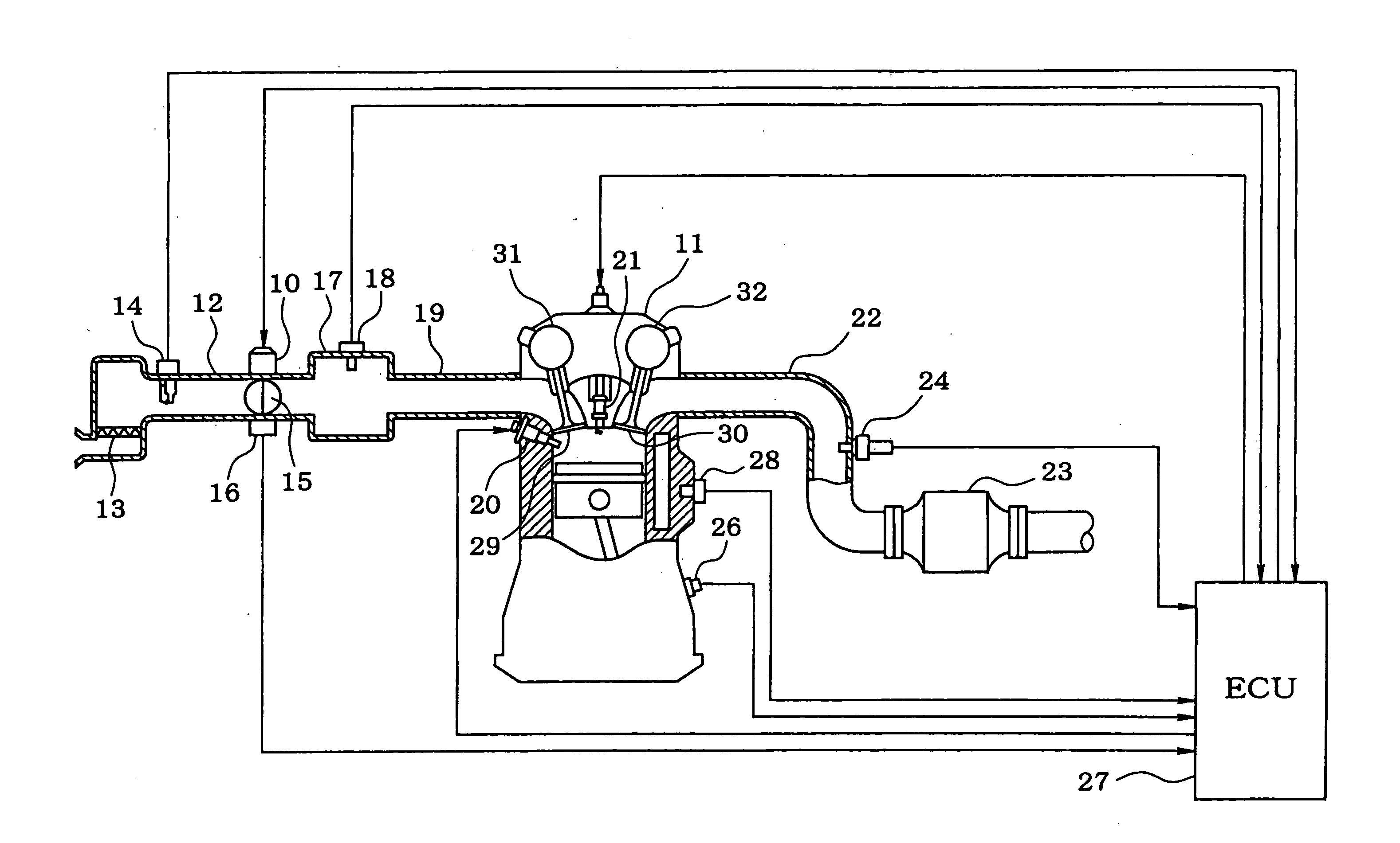
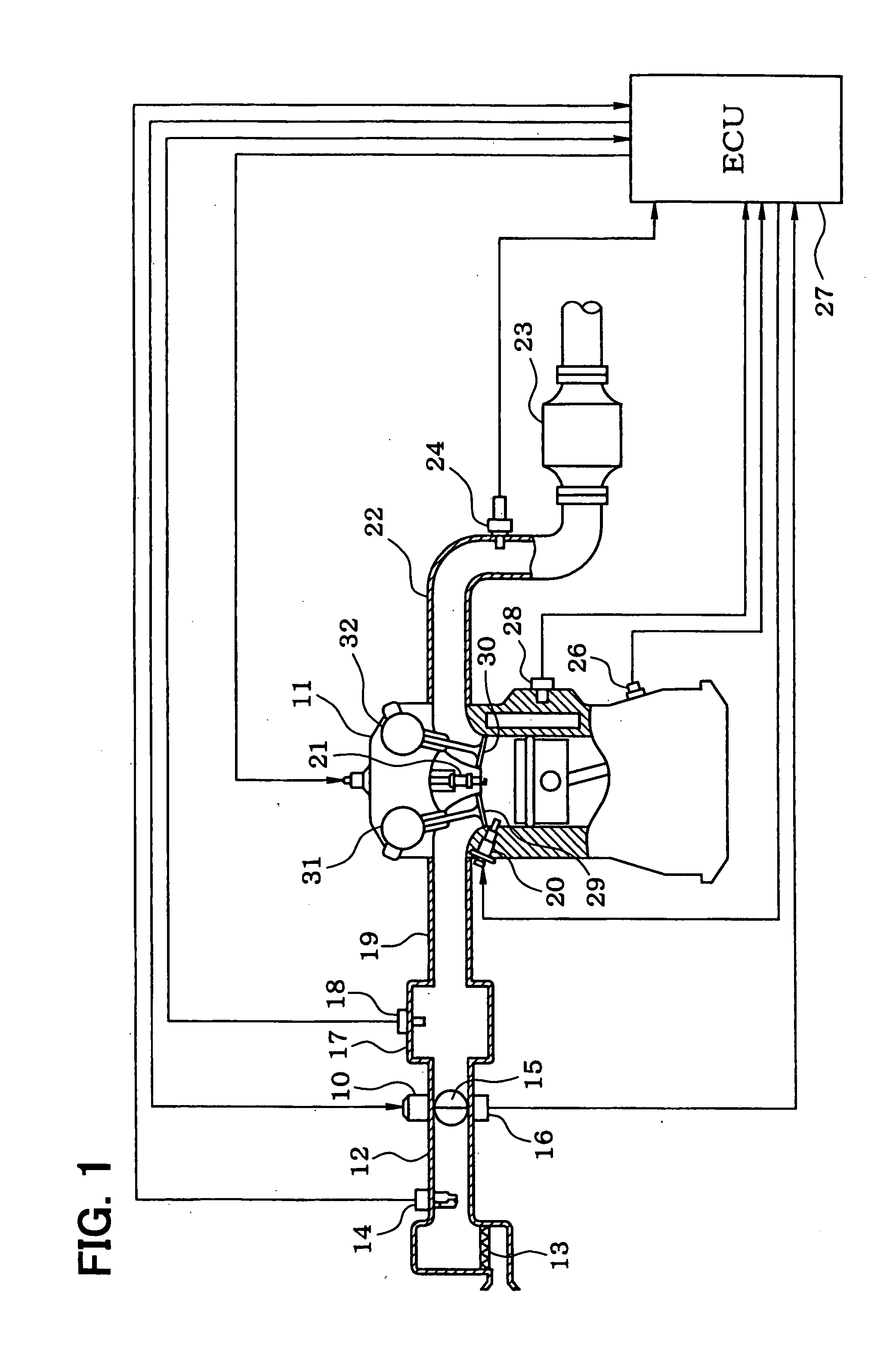
[0017]First, based on FIG. 1, a schematic configuration of the engine control system is explained. An air cleaner 13 is arranged upstream of an intake pipe 12 of an internal combustion engine 11. An airflow meter 14 detecting an intake air flow rate is provided downstream of the air cleaner 13. A throttle valve 15 driven by a DC-motor 10 and a throttle position sensor 16 detecting a throttle position are provided downstream of the air flow meter 14.

[0018]A surge tank 17 including an intake air pressure sensor 18 is provided down steam of the throttle valve 15. The intake air pressure sensor 18 detects intake air pressure. An intake manifold 20 is connected to the surge tank 17. A fuel injector 20 is mounted on each cylinder at a vicinity of an intake air port. A spark plug 21 is mounted on a cylinder head of the engine 11 corresponding to each cylinder to ignite air-fuel mixtur...

second embodiment

[0054]Then, a second embodiment of the present invention is explained referring to FIG. 4.

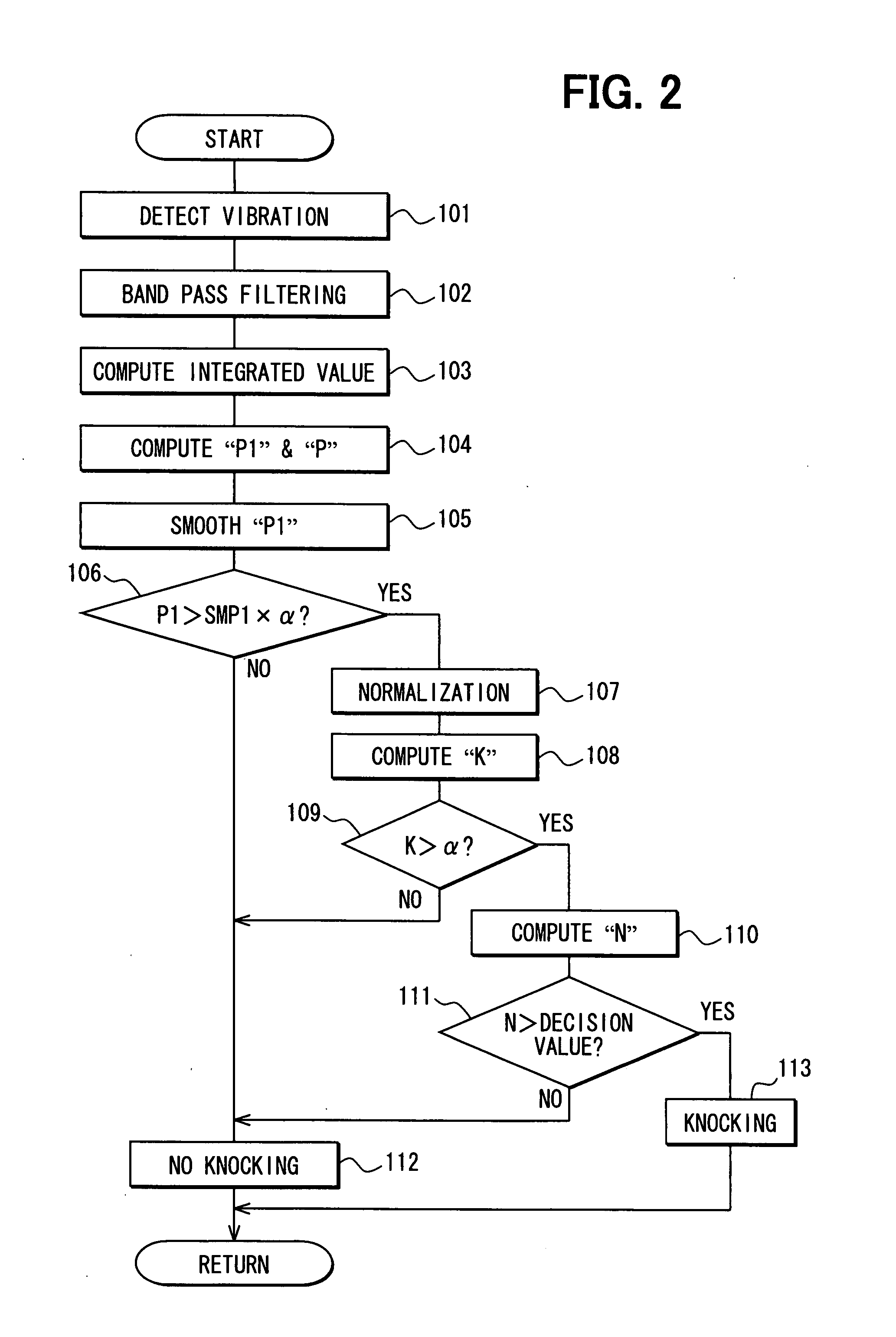
[0055]According to the second embodiment, the increment degree of the vibration strength of the primary frequency component is determined by comparing the peak value P1 of the primary frequency component with the maximum Pmax among peak values P2 to P4 of the 2nd order to the 4th frequency component by executing the knock determination program shown in FIG. 4.

[0056]In the knock determination program shown in FIG. 4, a band pass filter processing extracts the 1st to the 4th order frequency component from the output of the knock sensor 28. The integrated values which integrates the 1st to the 4th order frequency component by the specified crank angle for every specified crank angle, respectively is computed. The integrated value for every specified crank angle of the 1st to the 4th order frequency component is totaled, and the composite vibration waveform is generated (steps 201-203).

[0057]Then, ...


PUM


Abstract

A band pass filter processing extracts the vibration component (frequency component) of the 1st to the 4th order frequency band from the output of the knock sensor. A primary frequency band is established as the frequency band containing the fundamental frequency (primary resonance frequency) which is the lowest frequency of the knocking vibration frequencies. The 2nd to the 4th order frequency band is established as the frequency band containing the 2nd to the 4th order resonance frequency. Based on the vibration strength of the primary frequency component, the comparison result between the composite vibration waveform which compounded the 1st to the 4th order frequency component and the ideal knock waveform, and the vibration strength of the summation of the 1st to the 4th order frequency component, the noise and knocking are distinguished from each other with sufficient accuracy.

Description

CROSS-REFERENCE TO RELATED APPLICATION[0001]This application is based on Japanese Patent Application No. 2006-278315 filed on Oct. 12, 2006, the disclosure of which is incorporated herein by reference.FIELD OF THE INVENTION[0002]The present invention relates to a knock determining device and method for an internal combustion engine which determines whether a knock exists or not based on an output of the vibration sensor which detects a knocking vibration of the internal combustion engine.BACKGROUND OF THE INVENTION[0003]Generally, the knock determining device of the internal combustion engine has the knock sensor attached to the cylinder block of the internal combustion engine, and extracts the vibration component of the predetermined frequency band from the output of this knock sensor with the band pass filter. A knock determination is performed by comparing the peak value and integral value (that is, information on vibration strength) of the vibration component of this predetermin...

Claims


Application Information

Patent Timeline
IPC IPC(8): G01L23/22
CPCG01L23/225
Inventor TAKEMURA, YUUICHIOE, SHUHEIKANEKO, RIHITOKASASHIMA, KENJI
Owner DENSO CORP
Why Eureka
Try Eureka