Adjustable masonry anchor assembly for use with insulating concrete form systems

a technology of insulating concrete and masonry, which is applied in the direction of walls, building components, building repairs, etc., can solve the problems of not being able to adapt to use, rendering the attachment mechanism associated with the known connector inoperative in this particular application, and the construction of such known connectors not being compatible for use with icf systems, etc., to achieve the effect of flexibility and adjustmen

Active Publication Date: 2008-04-24
AIRLITE PLASTICS
View PDF15 Cites 56 Cited by
  • Summary
  • Abstract
  • Description
  • Claims
  • Application Information

AI Technical Summary

Benefits of technology

[0012]The attachment portion of the anchor member also includes an elongated slot located adjacent the tab member for receiving a tie wire member which can be adjustably positioned along the length of the slot so as to be positioned in alignment with the masonry mortar joint between the courses of brick or other masonry material as the masonry wall is being erected in front of the ICF formed wall system. These masonry tie wire members are embedded in the mortar between two courses of the brick or other masonry material and are fixedly secured thereto once the mortar hardens. Because the exact location of the mortar joint between two courses of brick or

Problems solved by technology

Such known connectors, however, are not particularly adaptable for use with the growing use of ICF systems commonly used today for both residential and commercial construction.
Use of the known masonry connectors such as the connectors disclosed in U.S. Pat. Nos. 4,869,043 and 5,392,581 are not easily adaptable for use with ICF wall systems

Method used


Image

  • Adjustable masonry anchor assembly for use with insulating concrete form systems
  • Adjustable masonry anchor assembly for use with insulating concrete form systems
  • Adjustable masonry anchor assembly for use with insulating concrete form systems

Examples


Embodiment Construction

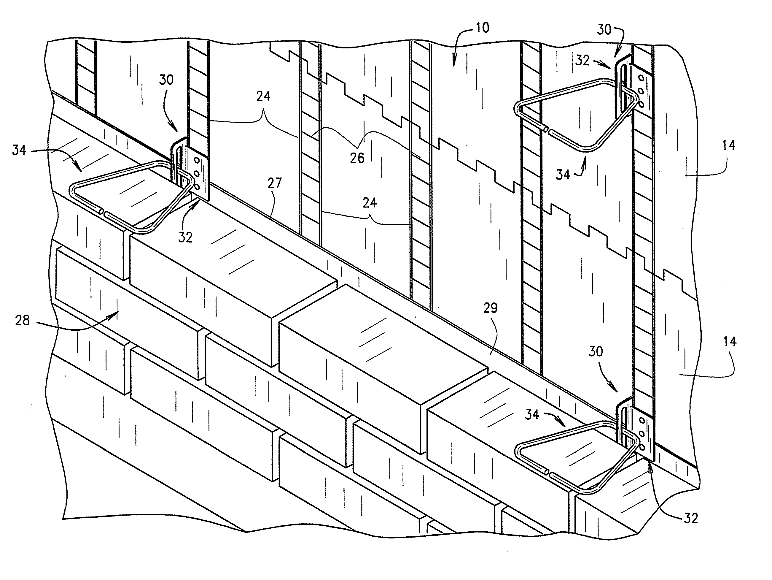
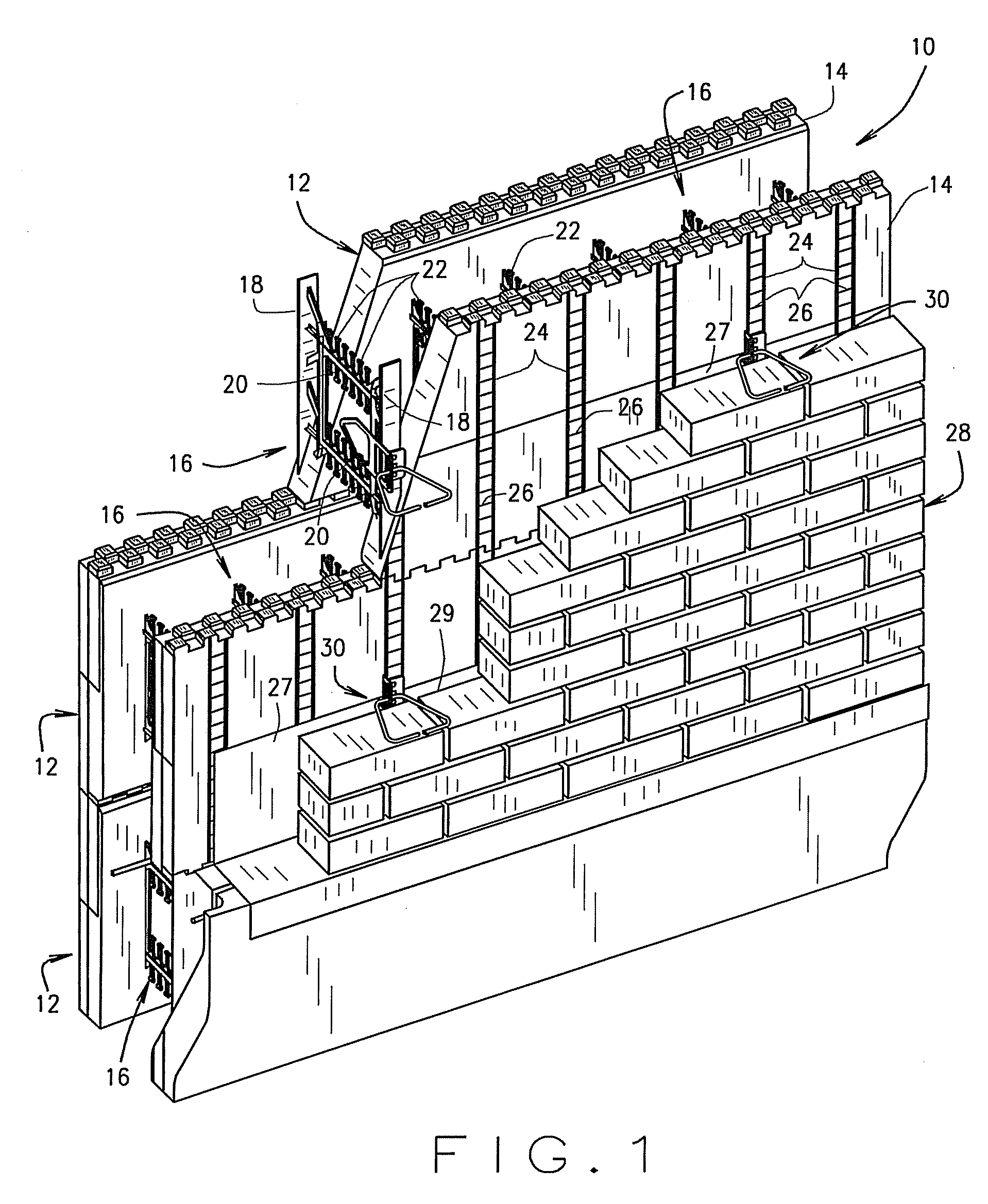
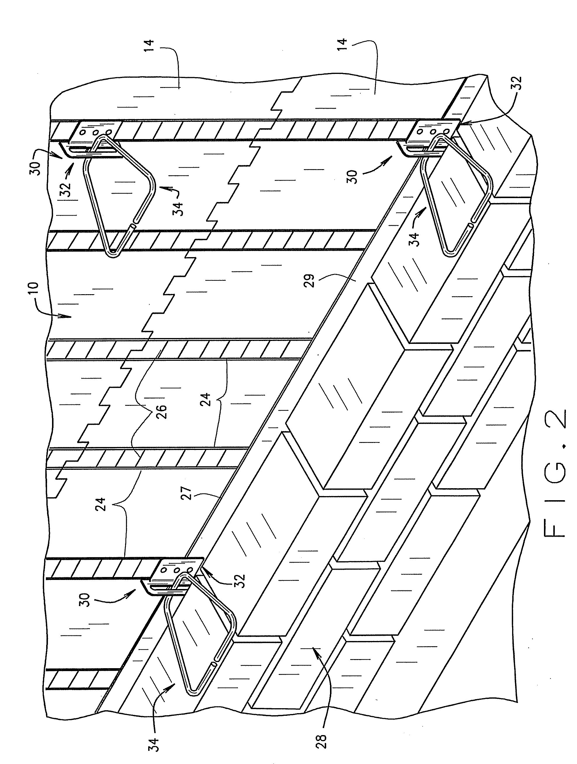
[0022]Referring to the drawings more particularly by reference numbers wherein like numerals refer to like parts, the number 30 in FIGS. 1-3 identifies one embodiment of an adjustable masonry anchor assembly constructed according to the teachings of the present invention. FIGS. 1 and 2 illustrate a typical use of the present anchor assembly 30 for joining or tying together a masonry structure such as the conventional brick wall structure 28 which is positioned and located in spaced apart relationship in front of a supporting back-wall structure 10 which is formed using a conventional ICF system. As best shown in FIG. 2, the brick wall or other masonry veneer 28 is positioned in front of the back-wall structure 10 so as to form a space or cavity 29 therebetween. As discussed below, this space or cavity 29 is sufficient to receive and accommodate the attachment portion 38 of the present anchor assembly 30 as will be hereinafter further explained.

[0023]The supporting back-wall structur...


PUM


Abstract

An anchor assembly for use in joining together a masonry wall structure and a supporting back wall structure wherein the back wall structure is preferably formed using insulated concrete form (ICF) blocks each having a pair of opposed ICF panels associated therewith, the anchor assembly including an anchor member and a tie member. The anchor member includes an anchor portion adapted to penetrate one of the ICF panels and having at least one opening associated therewith so as to lie between the opposed ICF panels when attached thereto for allowing poured concrete to flow therethrough, and an attachment portion having a tab member positioned and located to overlay an ICF panel flange member when the anchor member is inserted within the ICF panel, the tab member being attachable to the ICF panel flange member. The attachment portion further includes an elongated slot for receiving the tie member, the tie member being adjustably movable along the length of the slot so as to be positionable between the courses of brick or other masonry material associated with the masonry wall structure as the masonry wall structure is being erected.

Description

CROSS-REFERENCE TO RELATED APPLICATION[0001]This application claims the benefit of U.S. Provisional Patent Application No. 60 / 829,997, filed on Oct. 18, 2006, the disclosure of which is incorporated herein by reference.BACKGROUND OF INVENTION[0002]The present invention relates to a connector assembly for joining or tying together a masonry structure with a supporting back-wall structure and, more particularly, to an adjustable masonry anchor assembly for use with Insulating Concrete Form (ICF) systems wherein the present masonry anchor is embedded into the ICF system during the wall forming process.[0003]Brick, stone, and other masonry veneers or other exterior cladding is oftentimes used in construction to present a wide variety of different aesthetically pleasing exterior appearances to a building or other structure. Typically, this outer masonry wall is spaced from the supporting back-up wall forming a spacer cavity therebetween for insulation purposes. This outer masonry wall is...

Claims


Application Information

Patent Timeline
IPC IPC(8): E04B1/38
CPCE04B2/8617E04B1/4178
Inventor DOERR, KELVIN LESLIEPFEIFFER, HENRY E.
Owner AIRLITE PLASTICS
Why Eureka
Try Eureka