Protective lock structure

a technology of lock structure and lock body, applied in the direction of alarm locks, mechanical controls, instruments, etc., can solve the problems of high installation cost, multifarious equipment, difficult installation of traditional monitoring equipment, etc., and achieve the effect of free-flowing chang

a technology of lock structure and lock body, applied in the direction of alarm locks, mechanical controls, instruments, etc., can solve the problems of high installation cost, multifarious equipment, difficult installation of traditional monitoring equipment, etc., and achieve the effect of free-flowing chang

US20080092610A1Inactive Publication Date: 2008-04-24KUO CHUNG YI +1

Image

  • Protective lock structure
  • Protective lock structure
  • Protective lock structure

Examples


Embodiment Construction

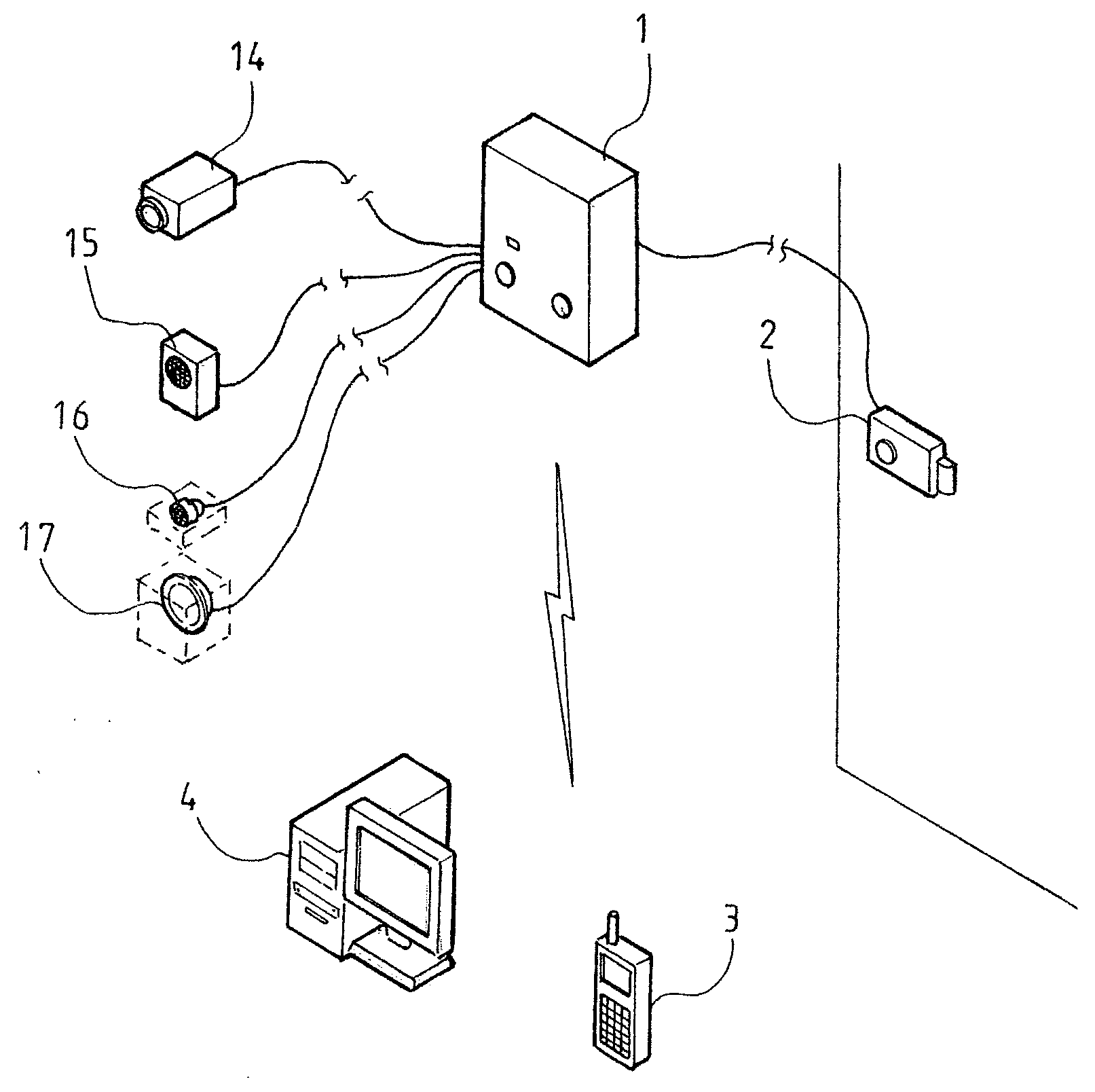
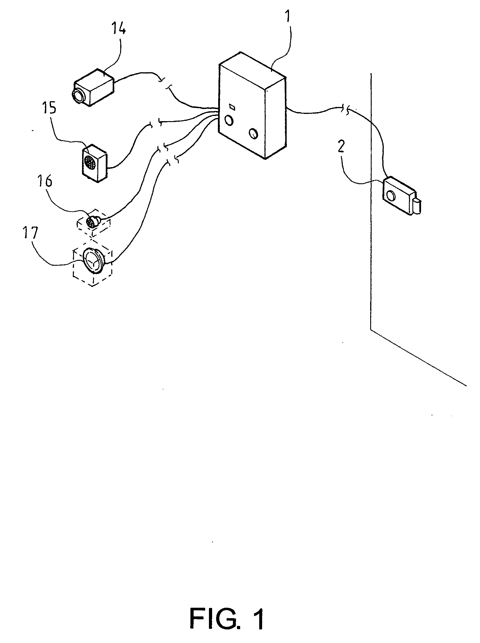
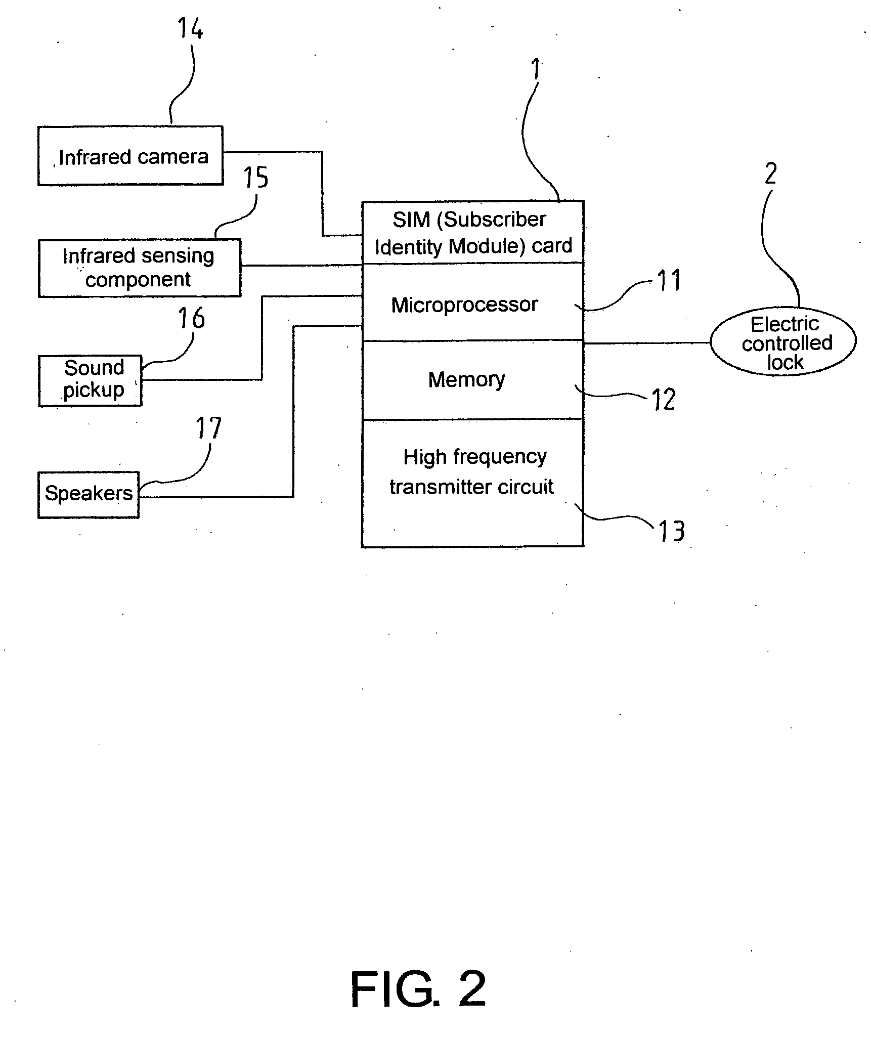
[0013]Referring to FIGS. 1 and 2, which show a main body 1 of the present invention, interior of which is disposed a control circuit assembled to comprise a SIM (Subscriber Identity Module) card 10, a microprocessor 11, a memory 12 and a high frequency transmitter circuit 13 (having GPRS (General Packet Radio Service), MMS (Multimedia Message Service), SMS (Short Message Service) functionality). The main body 1 is connected to monitoring equipment, including an infrared camera 14, an infrared hot body sensing component 15, a sound pickup and speakers 17 (moreover, the aforementioned monitoring equipment and the main body 1 form an integral body). Furthermore, the main body 1 is connected to an electric controlled lock 2 (an anode lock, a cathode lock, an electromagnetic lock, and so on), thereby fabricating a protective lock 100 that enables a cellular phone handset 3 to dial out a telephone number and preset code, which the control circuit of the main body 1 identifies and compares...


PUM


Abstract

A protective lock structure mainly including a main body, interior of which is disposed a control circuit assembled from a microprocessor, a memory, a high frequency transmitter circuit. The main body is connected to monitoring equipment, including an infrared camera, an infrared hot body sensing component, a sound pickup and speakers. Moreover, the main body is connected to an electric controlled lock, thereby enabling a cellular phone handset to dial out a telephone number and preset code, which the control circuit of the main body identifies and compares to ensure correctness before unlocking the electric controlled lock, thus providing a lock device with even greater safety and protective effectiveness.

Description

BACKGROUND OF THE INVENTION[0001](a) Field of the Invention[0002]The present invention relates to a protective lock structure, and more particularly to a protective lock structure that integrates future mobile communication, using a cellular phone handset to control unlocking, and is further provided with video and sound functionality and utility for real time video information transmission to electronic mailboxes.[0003](b) Description of the Prior Art[0004]Regarding current existing lock device structures, apart from the traditional lock device that uses a key to unlock and lock the lock device, other lock devices include: combination locks, card lock devices, and so on. However, regardless of the type of lock device, the unlocking structure of each is exposed to the exterior, such as a keyhole, a card swipe device, and so on, which present an opportunity that can be exploited by burglars. Hence, shortcomings exist in the safety aspect of such traditional lock devices. Furthermore,...

Claims


Application Information

Patent Timeline
24 Apr 2008
Publication
US20080092610A1
IPC
E05B45/06
CPC
E05B17/0079; E05B47/00; E05B2047/0095; G07C9/00166; G07C9/00309; G08B25/08; G07C2009/00793; G07C2209/64
Inventors
KUO, CHUNG-YI; WANG, KUO-TSO