
Hydraulic hybrid vehicle method of safe operation

a hybrid vehicle and hydraulic technology, applied in the direction of propulsion parts, mechanical equipment, transportation and packaging, etc., can solve the problems of high operating costs, high operating costs, and high cost of electric storage batteries currently available for hybrid vehicle operation

Inactive Publication Date: 2008-04-24
GOVERNMENT OF THE UNITED STATES OF AMERICA AS REPRESENTED BY THE ADMINISTATOR OF THE U S ENIVERONMENTAL PROTECTION AGENCY
View PDF11 Cites 35 Cited by
  • Summary
  • Abstract
  • Description
  • Claims
  • Application Information

AI Technical Summary

Benefits of technology

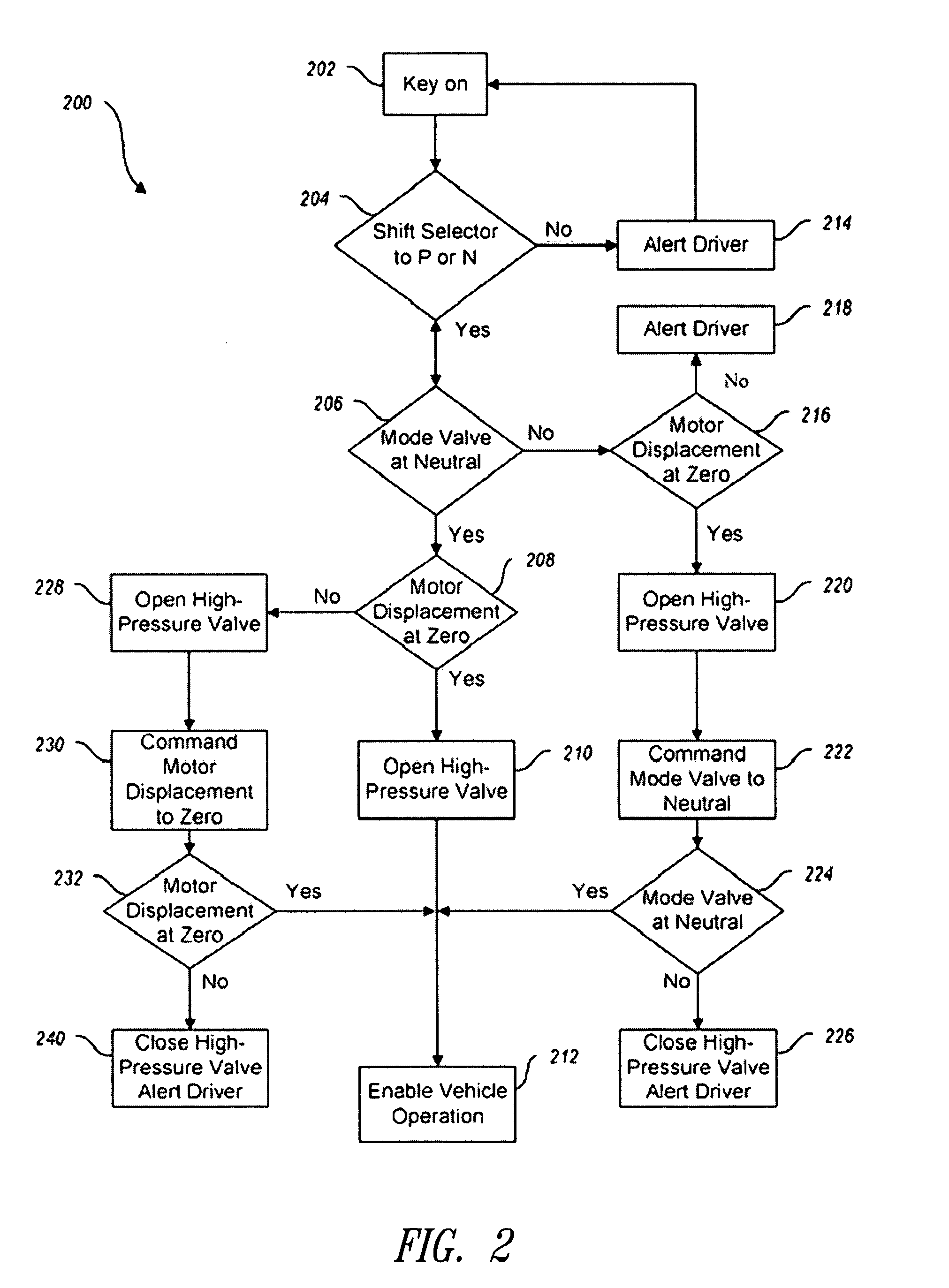
[0013]The disclosed embodiments include an initialization procedure for start-up of a hydraulic hybrid vehicle, as well as a shut-down procedure. Additionally, procedures for detecting and responding to failure of a motor, internal and external fluid leaks, and non-responsive actuation and mode control systems are provided.

Problems solved by technology

Because of this requirement for a high level of available power, the engines in most conventional vehicles spend most of their time operating well below their most efficient speed and load.
The potential for lower operating costs is due to the fact that electric storage batteries currently available for use in hybrid vehicle operation are expensive and have a limited lifespan, with potential replacement at significant cost to the vehicle owner.
The storage batteries are also an environmental concern because they contain large amounts of heavy metals that must be disposed of when the worn-out batteries are removed from the vehicles.
Hydraulic systems such as might be employed in hybrid vehicles do not employ components that inherently require replacement, nor do they employ large amounts of toxic or harmful substances.

Method used


Image

  • Hydraulic hybrid vehicle method of safe operation
  • Hydraulic hybrid vehicle method of safe operation
  • Hydraulic hybrid vehicle method of safe operation

Examples


Embodiment Construction

[0016]The present disclosure is directed to innovations and improvements in hybrid hydraulic technology. Accordingly, where reference is made to hybrid vehicles, or hybrid technology, it may be assumed that the reference is directed to hydraulic hybrid vehicles, in particular, unless otherwise noted. Aspects of the invention will be described with reference to a bent-axis pump / motor, such as is well known in the art, though, where a claim recites a motor, the scope of the claim includes any hydraulic machine that can be adapted to operate as claimed, and may include, for example, swash plate and radial piston machines.

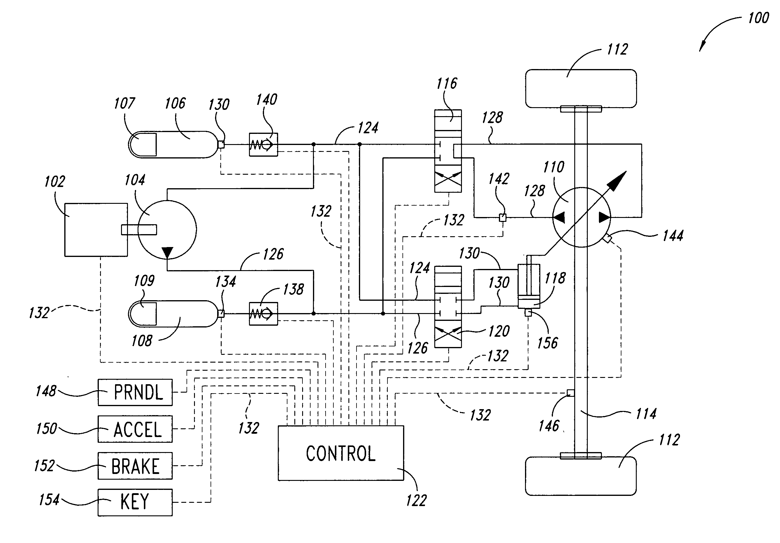
[0017]FIG. 1 is a simplified schematic diagram of a hydraulic hybrid vehicle system 100. The vehicle 100 includes an internal combustion engine (ICE) 102 whose output shaft is coupled to a hydraulic pump 104. The pump 104 is configured to draw low-pressure fluid from a low-pressure accumulator 106 (LPA) and pump the fluid at high pressure to a high-pressure accumulator...


PUM


Abstract

A hydraulic hybrid vehicle includes elements such as a hydraulic pump driven by an internal combustion engine and arranged to draw in low pressure fluid and pump the fluid at high pressure to an accumulator. A hydraulic motor is powered by the pressurized fluid. Safety processes are provided for detecting and addressing a number of conditions that may arise in the operation of the hydraulic hybrid vehicle, including an initialization procedure for start-up of the vehicle, a shut-down procedure, and procedures for detecting and responding to failure of the pump or motor, internal and external fluid leaks, and non-responsive actuation and mode control systems.

Description

BACKGROUND OF THE INVENTION[0001]1. Field of the Invention[0002]The present disclosure is directed to processes for safe operation of a hydraulic hybrid vehicle system, and in particular, to processes for detecting and / or addressing safety conditions arising out of operation of the vehicle.[0003]2. Description of the Related Art[0004]Significant interest has been generated, in recent years, in hybrid vehicle technology as a way to improve fuel economy and reduce the environmental impact of the large number of vehicles in operation. The term hybrid is used in reference to vehicles employing two or more power sources to provide motive energy to the vehicle. For example, electric hybrid vehicles are currently available that employ an internal combustion engine and a generator which generates electricity that can be stored in a battery of storage cells. This stored energy is then used, as necessary, to drive an electric motor coupled to the drive train of the vehicle.[0005]Hybrid vehicl...

Claims


Application Information

Patent Timeline
IPC IPC(8): B60K17/00B60W30/18
CPCB60K6/12B60L2240/486B60W30/18027B60W2540/10B60W2540/12Y02T10/6282F16H61/4096F16H61/4192F16H2312/20Y02T10/6208B60W2540/16Y02T10/62B60K2006/126B60W30/18054
Inventor T
Owner GOVERNMENT OF THE UNITED STATES OF AMERICA AS REPRESENTED BY THE ADMINISTATOR OF THE U S ENIVERONMENTAL PROTECTION AGENCY
Learn More