

Method of manufacturing a head assembly
- Summary
- Abstract
- Description
- Claims
- Application Information
AI Technical Summary
Benefits of technology
Problems solved by technology
Method used
Image

Examples
first embodiment
[0031]Preferred embodiments of a method of manufacturing a head assembly will now be described with reference to the attached drawings. The expression “head assembly” in the present embodiment refers to a so-called HGA (Head Gimbal Assembly).
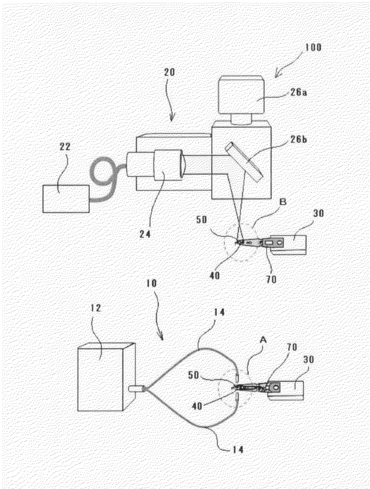
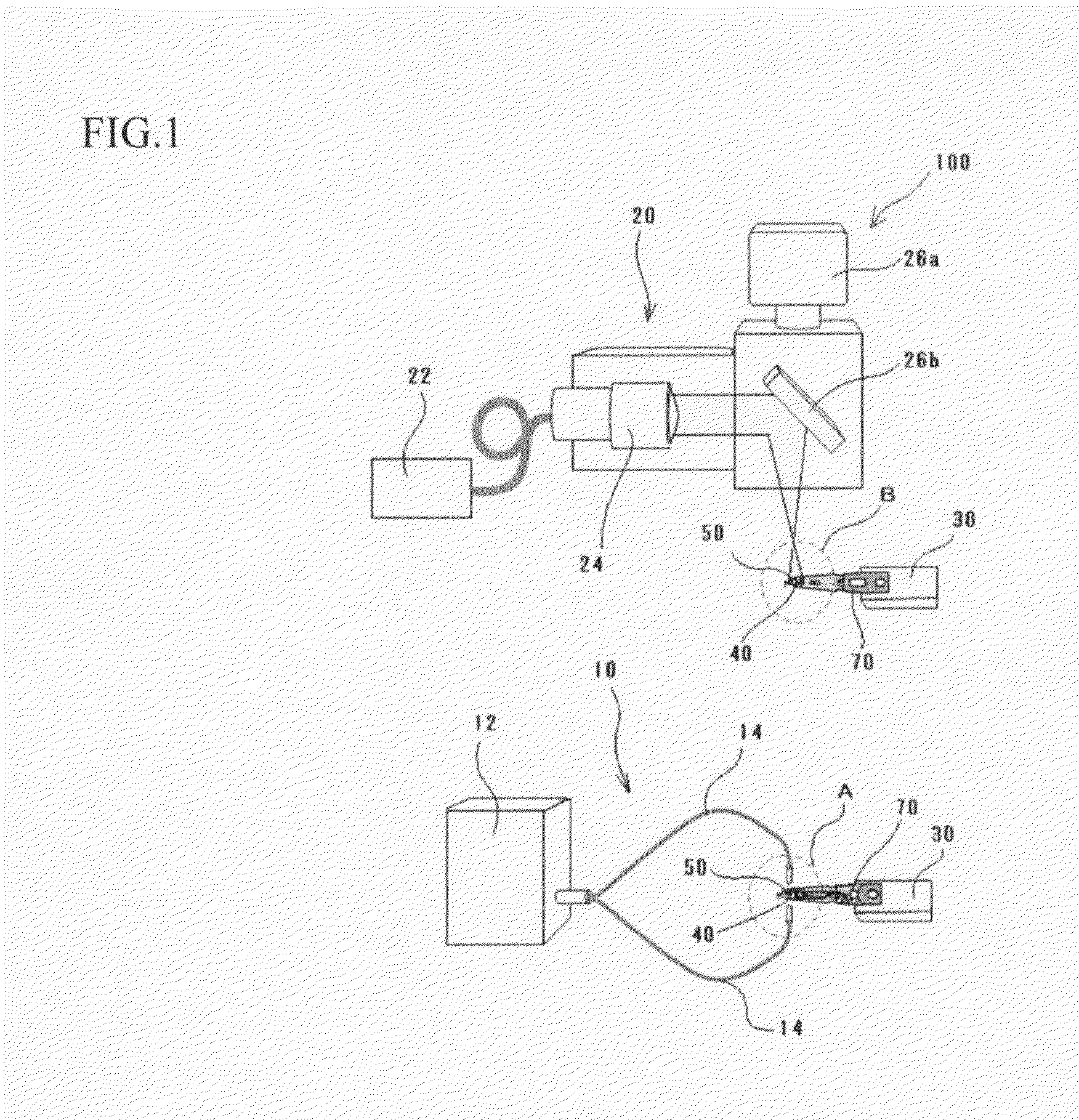
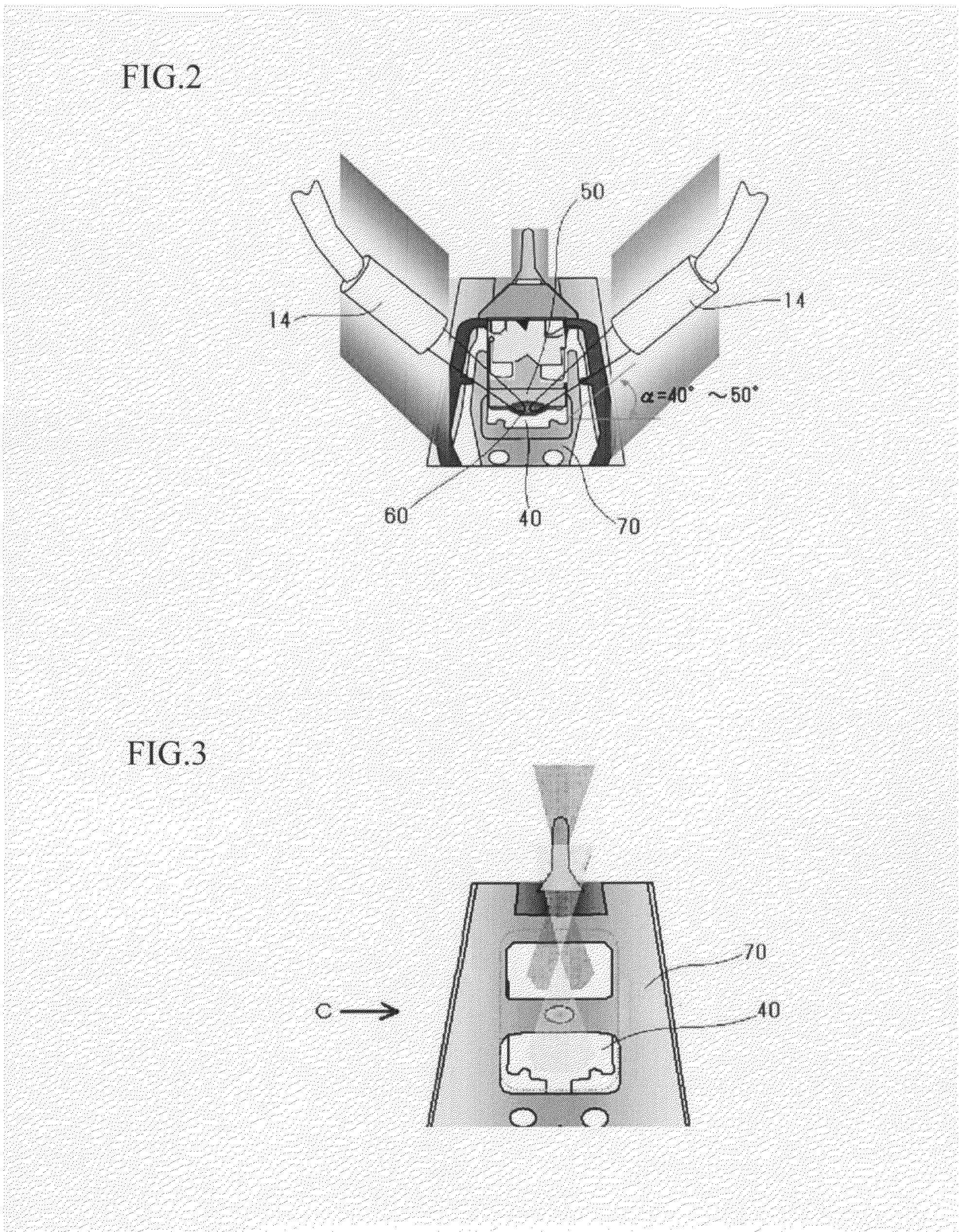
[0032]FIG. 1 is a view showing the construction of an apparatus for assembling a head assembly according to the present embodiment. FIG. 2 is an enlarged view of part A in FIG. 1. FIG. 3 is an enlarged view of part B in FIG. 1. FIG. 4 is a view when looking in the direction of the arrow C in FIG. 3. FIG. 5 is a graph showing the relationship between the output of laser light during irradiation and the time axis.
[0033]The apparatus 100 for assembling a head assembly in the present embodiment includes a UV-ray irradiating unit 10, a laser light irradiating unit 20, and a conveying unit 30.
[0034]The UV-ray irradiating unit 10 hardens one part of adhesive (thermosetting UV adhesive) 60 interposed between a gimbal 40 and a slider 50 equipped with a h...
second embodiment
[0051]In the first embodiment described above, an apparatus 100 for assembling a head assembly where the laser light irradiating unit 20 includes a fiber collimator 24 as a converging lens and a method of assembling a head assembly using such apparatus have been described. However, with the construction described above, when the adhesive 60 is applied at a plurality of positions on the gimbal 40, after the adhesive 60 at one position has been irradiated with laser light, the setting angle of the reflector 26b needs to be changed so that the adhesive 60 at another position can be irradiated with laser light. Accordingly, the time taken by the thermosetting process (the second hardening process) for the adhesive 60 increases in proportion to the number of positions where the adhesive 60 is applied.
[0052]In this case, a beam-splitting lens may be disposed in the laser light irradiating unit 20 in addition to the converging lens. By doing so, the control unit (not shown) of the laser li...
third embodiment
[0054]In the embodiments described above, an optical lens (a converging lens, such as a fiber collimator, or a beam-splitting lens) is disposed between the semiconductor laser 22 and the reflector 26b to irradiate predetermined positions on the gimbal 40 with laser light. However, it is possible to use a construction where the laser light emitted from the semiconductor laser 22 is transmitted onto predetermined positions on the gimbal 40 by passing the laser light through a shield plate 80 in which slits 82 are formed after the laser light has been reflected by the reflector 26b. FIG. 7 is a diagram showing a state where the gimbal is irradiated with laser light that has passed through a shield plate.
[0055]By using the shield plate 80 with the slits 82 in place of an optical lens such as a converging lens or a beam-splitting lens, it is possible to prevent unintentional heating of the gimbal 40 at positions aside from the application positions of the adhesive 60, and therefore defor...
PUM
 Abstract
Description
Claims
Application Information