Combustor and multi combustor including the combustor, and combusting method

a gas turbine and combustor technology, applied in the direction of combustion using lump and pulverulent fuel, combustion types, lighting and heating apparatus, etc., can solve the problems of increasing the maintenance and repair costs of gas turbines, difficult to reach stable combustion conditions of lean premixed flames, and enmity of people around power plants, so as to enhance fuel flexibility

Inactive Publication Date: 2008-05-01
KOREA ELECTRIC POWER CORP
View PDF8 Cites 19 Cited by
  • Summary
  • Abstract
  • Description
  • Claims
  • Application Information

AI Technical Summary

Benefits of technology

[0011]Therefore, the present invention has been made in view of the above problems, and it is an object of the present invention to provide a multi fuel nozzle of a gas turbine combustor with a variable jetting hole diameter capable of enhancing fuel flexibility in a multiple fuel system for applying two or more fuels to a gas turbine at the same time.

Problems solved by technology

Further, it is very difficult to reach stable combustion conditions of the lean premixed flame.
Thus, there are problems such as damage of gas turbine parts due to abnormal combustion and large pressure variation or heat loss of parts and life reduction due to high-temperature flow (hot gas), thereby causing an increase in the maintenance and repair costs of a gas turbine.
Thus, it may incur the enmity of the people around a power plant.
When the fuel is applied to the gas turbine power plant, the combustor may be burnt out due to the backfire of the flame.
However, in the case of heavy oil power generation, the power generation cost is expensive and a noxious exhaust gas is largely generated.

Method used


Image

  • Combustor and multi combustor including the combustor, and combusting method
  • Combustor and multi combustor including the combustor, and combusting method
  • Combustor and multi combustor including the combustor, and combusting method

Examples


Embodiment Construction

[0024]Hereinafter, an embodiment of the present invention will be described with reference to the accompanying drawings.

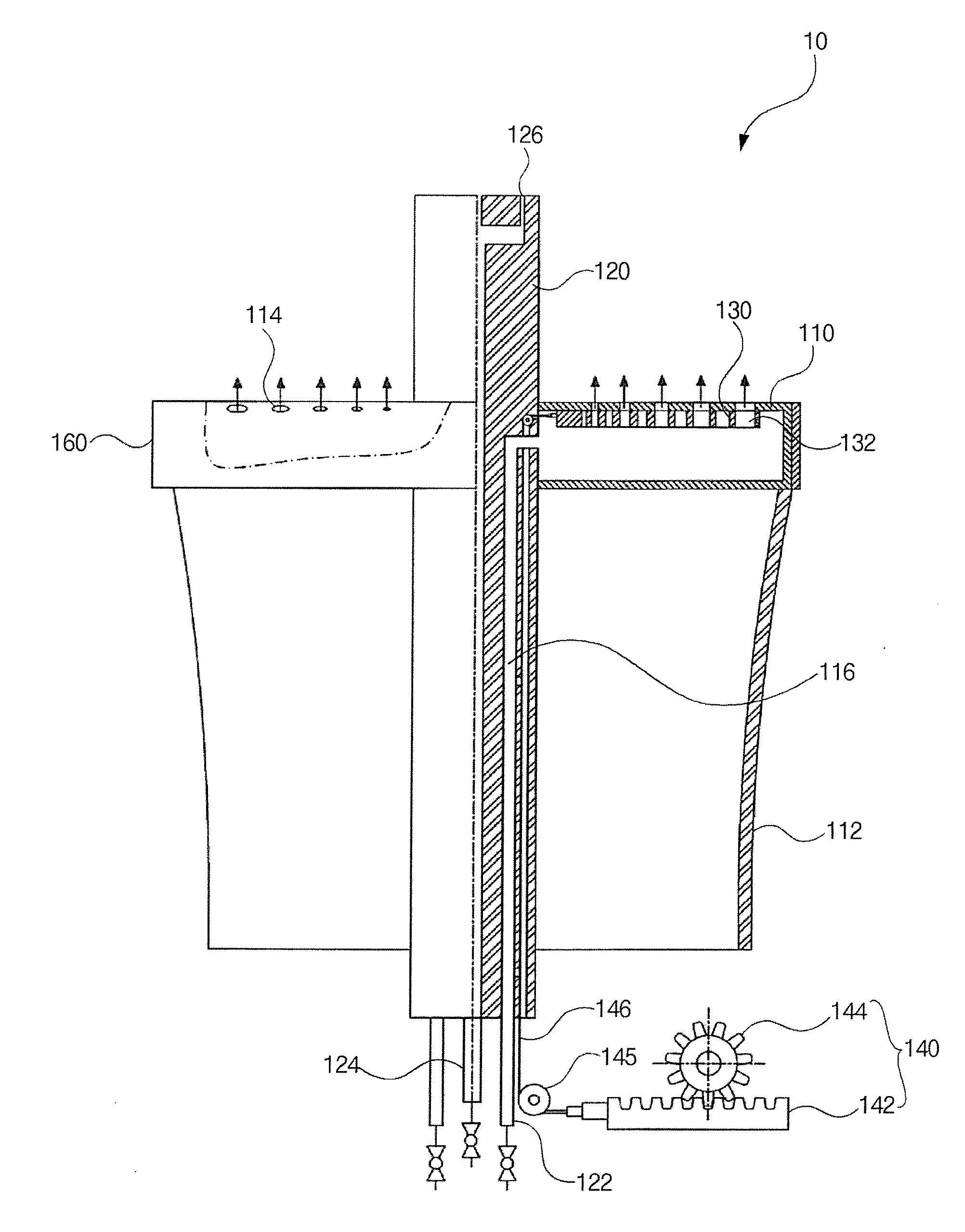
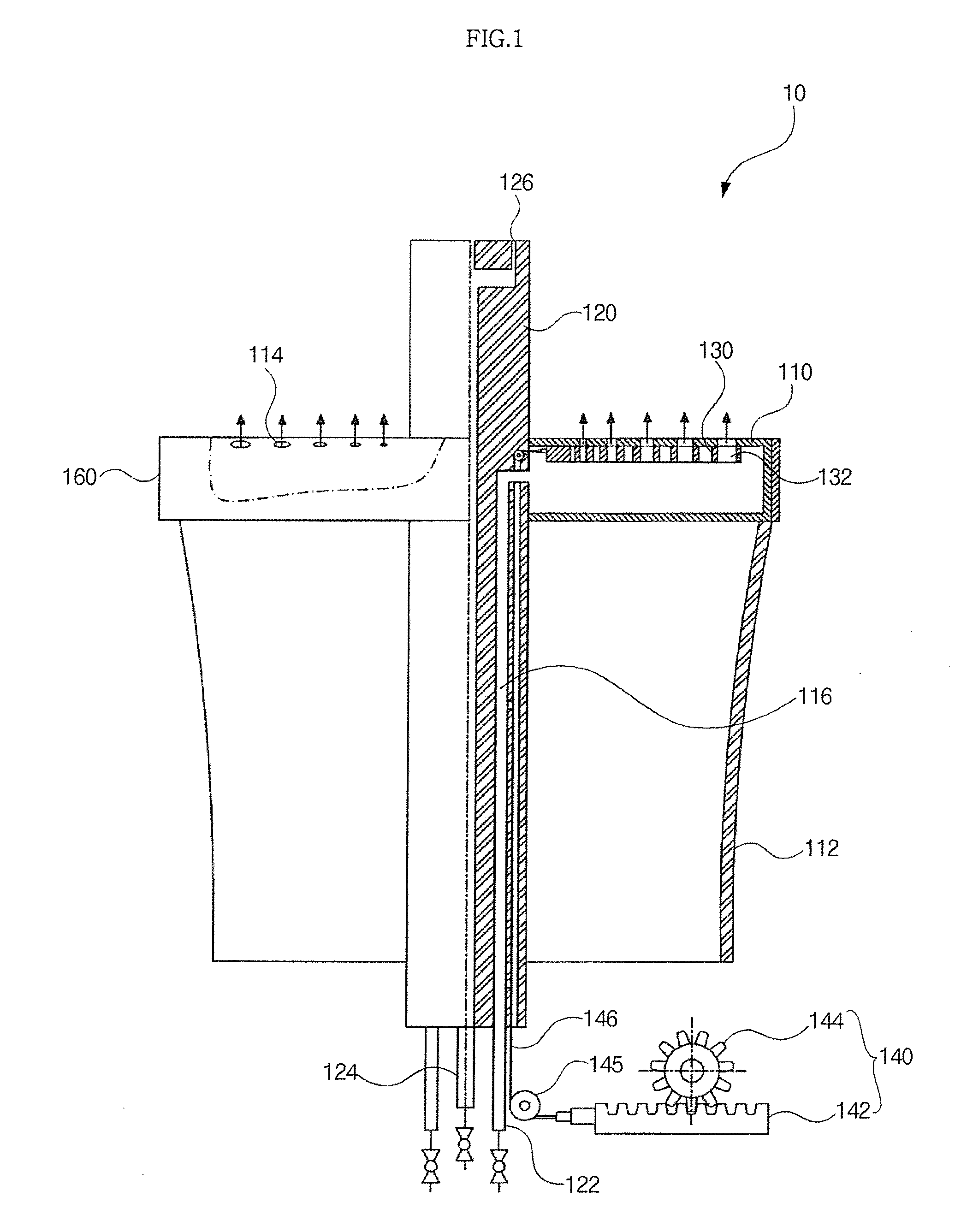
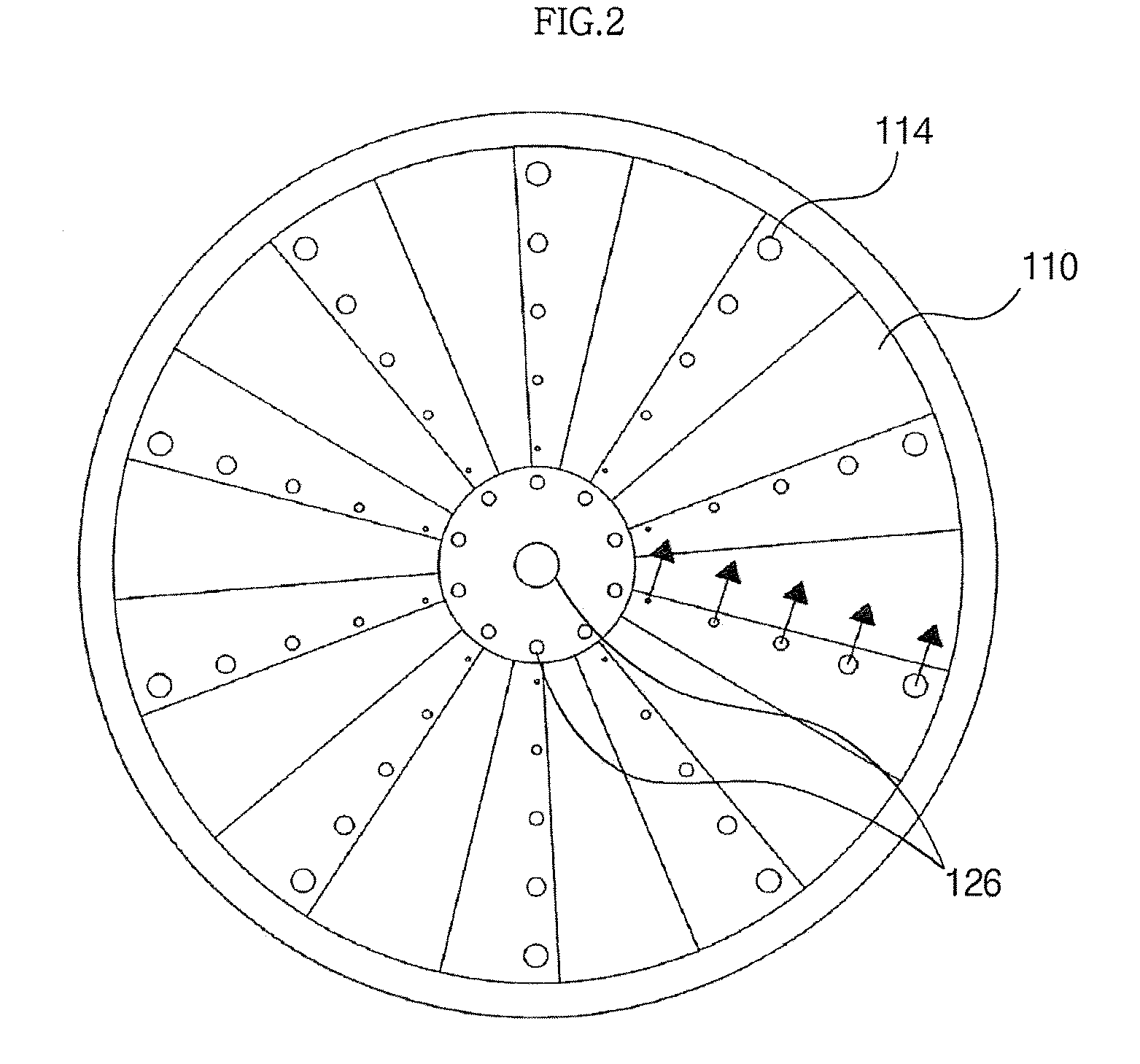
[0025]As shown in FIGS. 1 to 4, a variable dual fuel nozzle 10 includes swirling wings 110, a central shaft 120, a switching plate 130, a driving unit 140 and a casing 160.

[0026]That is, a plurality of swirling wings 110 is disposed along an outer peripheral surface of an upper portion of the central shaft 120. Then, a plurality of main fuel injection holes 122 and a pilot fuel injection hole 124 are disposed at a lower end of the central shaft 120 to pass through a central portion of the central shaft 120 from a lower portion to an upper portion. A plurality of pilot fuel jetting holes 126 is formed at an upper portion of the central shaft 120 to be connected to the pilot fuel injection hole 124. The main fuel injection holes 122 and the swirling wings 110 are connected to each other using a fuel channel 116. In this case, preferably, the main fuel injection holes...


PUM


Abstract

A dual fuel nozzle of a gas turbine combustor with a variable jetting hole diameter is disclosed. The combustor includes a plurality of swirling wings disposed along an outer peripheral surface of a central shaft to have at least one main fuel jetting hole, an air duct positioned at the lower side of the swirling wings to supply air to the swirling wings, a pilot fuel injection hole and jetting hole formed to pass through a central portion of the central shaft to supply a pilot fuel, a switching plate disposed inside the swirling wings to vary the size of the main fuel jetting hole, a driving unit disposed to be connected to the switching plate to move a position of the switching plate, and a casing containing the swirling wings, the air duct, the switching plate and the driving unit. It is possible to enhance fuel flexibility in a multiple fuel system for applying two or more fuels to a gas turbine at the same time.

Description

BACKGROUND OF THE INVENTION[0001]1. Field of the Invention[0002]The present invention relates to a dual fuel nozzle of a gas turbine combustor with a variable jetting hole diameter, and more particularly to a dual fuel nozzle of a gas turbine combustor with a variable jetting hole diameter capable of enhancing fuel flexibility in a multiple fuel system for applying two or more fuels to a gas turbine at the same time.[0003]2. Description of the Related Art[0004]Recently, development of various clean fuels has been conducted in many research institutions of the world to solve an emission problem of an energy source and an environmental problem. Many fuels such as biomass, a coal gas, GTL (Gas To Liquid Fuel) and CTL (Coal To Liquid Fuel) have been developed and commercialized recently. Also, the research and development have been conducted in a consumption field with the manufacture of the fuels.[0005]A dry low NOx gas turbine employs a lean premixed combustion method, wherein a local...

Claims


Application Information

Patent Timeline
Patent Type & Authority Applications(United States)
IPC IPC(8): F02C9/26F23R3/04
CPCF23C7/004F23D14/58F23D14/60F23R3/36F23R3/14F23R3/286F23D17/002F02C9/32F02C9/38F23R3/28
Inventor LEE, MIN-CHULCHUNG, JAE-HWASEO, SEOK-BINJOO, YONG-JINKIM, JONG-JINAHN, DAL-HONG
Owner KOREA ELECTRIC POWER CORP
Why Eureka
Try Eureka