
Internal support structure for an internal combustion engine

a technology for internal combustion engines and support structures, which is applied in the direction of positive displacement engines, machines/engines, mechanical equipment, etc., can solve the problems of loss of available power, catastrophic engine failure, and potential injury to users and/or bystanders, and achieve the effect of increasing usable power outpu

Inactive Publication Date: 2008-05-01
OELERICH TIMOTHY D
View PDF14 Cites 8 Cited by
  • Summary
  • Abstract
  • Description
  • Claims
  • Application Information

AI Technical Summary

Benefits of technology

[0013]It is an object of the present invention to provide a structure for strengthening and stabilizing a crankshaft in a multi-cylinder internal combustion engine which improves upon the aforementioned limitations or problems encountered with the prior art while simultaneously increasing usable power output.
[0014]Another object of the present invention is to provide a main bearing cap and crankshaft supporting structure for a multi-cylinder engine which ties together the main bearing caps and the engine skirt with a one piece hardened steel plate in order to stabilize and minimize the vibration and elastic deformation of the crankshaft and main bearing caps when the engine is used in a high power output mode.
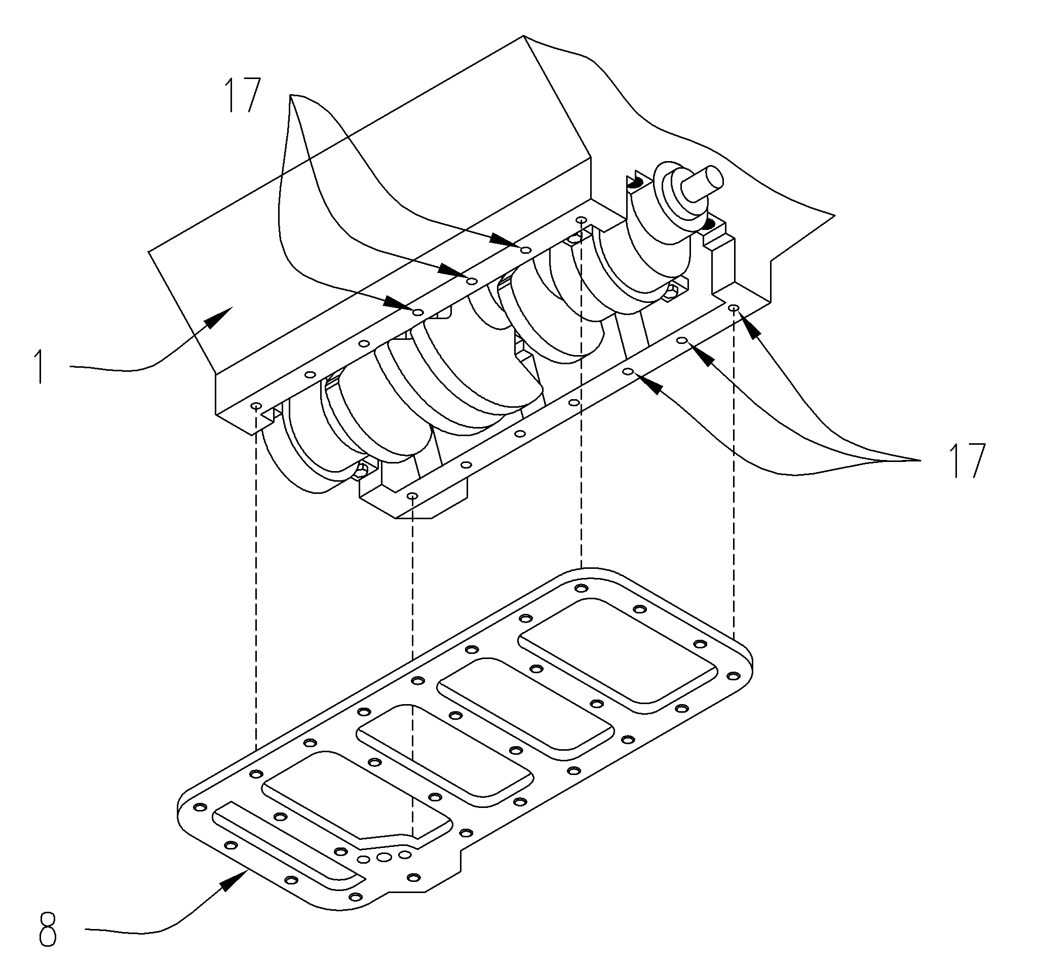
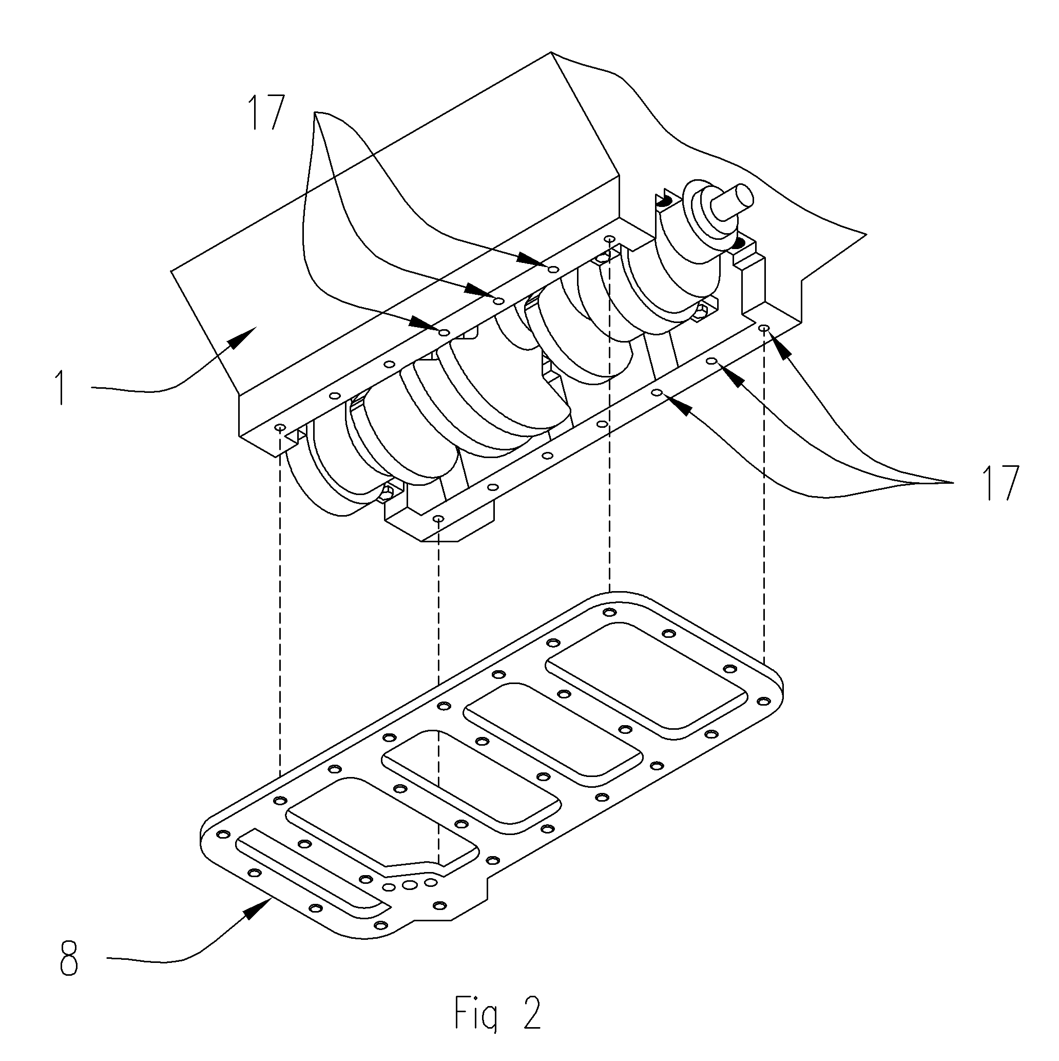
[0015]According to the present invention, there is provided a one piece high strength steel plate with sufficient opening for the crankshaft throws and counterweights to rotate through without interference, openings for the oil pump shaft and bolts and openings to accept new oil pan studs and main bearing cap studs. The main bearing cap studs being utilized to interconnect the engine block to the main bearing caps which are connected to a spacer washer which is then connected to the reinforcement plate of the present invention, all of which is tied together with the lock washers and jam nuts. This arrangement thereby ties 4 of the 5 of the main bearings caps together with a solid structure. The oil pan studs are then used to tie the reinforcement plate to the skirt with lock nuts in the counter bored holes of the reinforcement plate. This arrangement further stabilizes and reinforces the main bearing caps by tying the main bearing caps to the engine skirt through the use of the reinforcement plate. The oil pan is then attached to the oil pan studs with serrated flange nuts.
[0016]With the structure thus constituted in accordance with the present invention, as the engine skirt is directly secured to the reinforcement plate, which is also directly secured to the main bearing caps, the flexure, vibration and elastic deformation normally encountered in the crankshaft and main bearing caps is significantly reduced by the rigidity of the new structure. Furthermore, as the engine skirt is directly tied to the reinforcement plate, undesirable vibrations of each of the engine skirt portions are effectively suppressed.

Problems solved by technology

However, in use at high RPM and high pressure and torque, the crankshaft bearings, caps and related engine block mating surfaces actually deform elastically into an egg shaped oval.
This condition can cause a loss of available power as well as failure of the engine if the deformation of the caps and engine block is too great, thereby creating a catastrophic failure of the engine and potential injury to the user and / or bystanders.
Furthermore, the plate is not secured to the lower engine block skirt.
While Hayashi describes the use of ferrous metal, the metal he describes are relatively low strength, i.e. cast iron or mild steel.
Furthermore, as the reinforcement is integrated with the block, it cannot serve to tie the main bearing caps together after the block has been cast.
A further embodiment includes baffles that are attached between the bearing cap beams, however, both embodiments still require multiple beam components rather than a single unitary construction.

Method used


Image

  • Internal support structure for an internal combustion engine
  • Internal support structure for an internal combustion engine
  • Internal support structure for an internal combustion engine

Examples


Embodiment Construction

[0027]The present invention comprises a reinforcement plate, and associated fasteners, for the lower end (or crankshaft location) of a reciprocating engine block. The present invention fastens to four (4) of the five (5) main bearing caps, thereby stiffening the main bearing caps, and to the lower engine block skirt between the engine block skirt and the oil pan, thereby further immobilizing the main bearing caps relative to the lower engine block and restricting the movement which would otherwise occur when the engine is in operation. The result is a substantially increased rigidity to the engine block and main bearing caps along with greater resistance to any elastic deformation of the main bearing caps and main bearings.

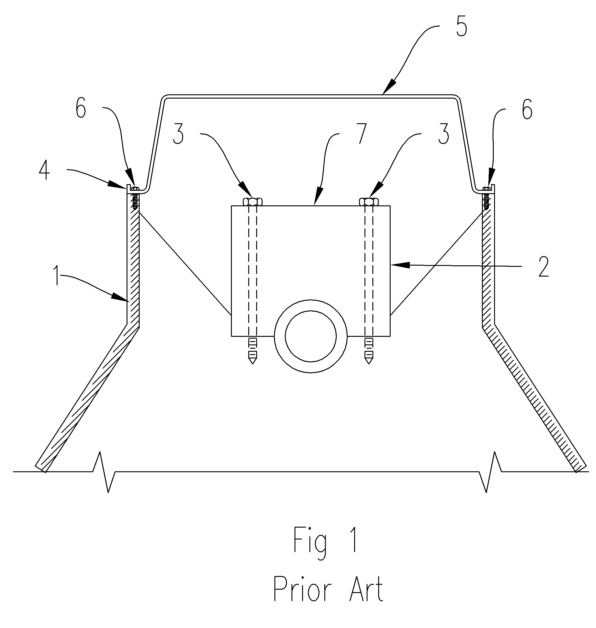
[0028]FIG. 1 depicts a prior art cross-sectional end view of a Ford FE engine block 1 with a main bearing cap 2 and an oil pan 5. The main bearing caps 2 are attached to the engine block 1 with bolts 3. The main bearing cap top surface 7 is in a close, but not exa...


PUM


Abstract

A reinforcement plate for a reciprocating engine that greatly reduces the elastic and plastic deformation of engine block components when the engine is run at high rpm and force is provided which reduces structural fatigue thereby increasing available horsepower. The one piece reinforcement plate ties together the main bearing caps to each other and to the engine block skirt, thereby increasing the rigidity of the main bearing caps and reducing the vibration of the engine. Crankshaft counterweight and crankshaft throw clearance openings, as well as other clearance areas, are provided in the reinforcement plate.

Description

BACKGROUND OF THE INVENTION[0001]In the area of big block and other high performance gasoline motors such as those utilized in automobile racing, boats and other applications, the participating individuals or teams often design the engines to their own specifications. In many instances, these designs are kept highly classified and secret from others in order to provide the individual or racing team with a competitive advantage. In other cases, an individual may desire to improve the performance of their engine by modifying the engine to provide greater horsepower than the engine was originally designed for.[0002]In automobile racing, for example, the engines are modified to the point that some do not even last through a specific race. These engines are typically modified to the structural limits of the design and materials in use. During actual running of the engines, they are run at their highest or near highest RPM (revolutions per minute) in order to generate the greatest horsepo...

Claims


Application Information

Patent Timeline
Patent Type & Authority Applications(United States)
IPC IPC(8): F02F7/00F01B1/00F16C9/02
CPCF01M11/0004F16C9/02F02F7/0053F01M2011/002
Inventor OELERICH, TIMOTHY D.
Owner OELERICH TIMOTHY D
Learn More